Of course! The wavelengths are in excess of 10 or 12 feet and the spacing is a fraction of that.
8 or 10 feet? A sealed dual opposed has 3 feet of spacing (maximum).
thanks for the explanation of how the LP filter works.
thanks for the explanation of how the LP filter works.
There is confusion here.
The spacing between the opposed drivers is a matter of inches. The wavelengths are at least 100's of inches. So it is safe to assume they are close enough so the disortion is effectively out of pahse and therefore cancelled.
I did not explain why the plenum (cavity) creates a LPF
The spacing between the opposed drivers is a matter of inches. The wavelengths are at least 100's of inches. So it is safe to assume they are close enough so the disortion is effectively out of pahse and therefore cancelled.
I did not explain why the plenum (cavity) creates a LPF
Last edited:
The closer the two drivers are to each other, the higher in frequency you will get the benefits of cancelling distortion (excuse the poor grammar).
You need to be realistic however. The distortion components at the higher freqs are being attenuated by the plenum (the cavity itself acts as a LP filter).
Please explain a low pass filter.
Indeed, very confusing: "distortion is effectively out of phase"???There is confusion here.So it is safe to assume they are close enough so the disortion is effectively out of pahse and therefore cancelled
Indeed, very confusing: "distortion is effectively out of phase"???
Think it through ...
A common cause of 2nd harmonic distortion results from the driver not "being equal" when the cone movement is inward vs outward. What the push-pull configuration does is put these distortion components (non-linearities) in opposite phase to each other. Hence, the cancellation.
I understand the cancellation, buy why do they need to be inches close to each other rather than a foot or 2 away?
I am a bit lost with all the discussion going on here. The one unit we have seen a photo of looks to me to be an ordinary bass reflex box with the two speakers mounted , one on the inside and one of the outside of a smaller box, but out of phase with eachother, the smaller box being inside the bass reflex box with one narrow side of the smaller box, the actual slot, open to the room. In no way is the smaller box 24 or more inches tall as shown in the last pdf. In no way is the volume of the smaller box, i.e the plenum before the actual slot, connected to the volume of the larger box. From the point of view of the plenum and slot as I see it, it is irrelevant whether the box is sealed or bass reflex.
Am I not seeing it correctly?
jamikl
Am I not seeing it correctly?
jamikl
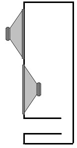
The PPSL is a slot loaded manifold like in the picture above. There is a plenum in the middle of the enclosure where the speakers are very close.
I suggested and my question was why not use a regular dual sealed with opposing drivers. Invert 1 of the drivers to face into the box.
As someone said, the wavelengths are 8 and 10 feet long, so why do the driveres NEED to be so close, to get the cancellation?
Vented and sealed are both ok. Some users are having difficulty modelling the build with a 6th order vented designed.
"Some users are having difficulty modelling the build with a 6th order vented designed. "
Only because they are trying to make it difficult.
Decide what you want, sealed, vented, equalized vented (6th order), or dipole.
Ignore the volume of the plenum.
Model the drivers loaded as above.
Done.
Only because they are trying to make it difficult.
Decide what you want, sealed, vented, equalized vented (6th order), or dipole.
Ignore the volume of the plenum.
Model the drivers loaded as above.
Done.
Hawkson the problem in your example is the relation between frequency and its wavelength. It will work for coupling of the drivers but not in relation to PPSL effect.
The PPSL works on the principal of loading the same air molecules ('captured' air in a slot) while in traditional PP setting they don’t. The smaller (volume) the plenum the wider the effect in frequency becomes (and in the same time drop its upper limit, still following ).
).
However, if you make the opening to small the pressure inside becomes to high. This will result in air resistance (friction -> heat) -> higher airmass -> lower SPL.
Secondly, there are also physical relations between the drivers that become more important in Djk's PPSL. But that's a much longer story and needs more understanding of the push-pull in relation to impulse behaviour, system damping and time domain (distance related).
But it's 9:15 AM and I'm very tired Hopefully I didn't make to many mistakes...
The PPSL works on the principal of loading the same air molecules ('captured' air in a slot) while in traditional PP setting they don’t. The smaller (volume) the plenum the wider the effect in frequency becomes (and in the same time drop its upper limit, still following
). However, if you make the opening to small the pressure inside becomes to high. This will result in air resistance (friction -> heat) -> higher airmass -> lower SPL.
Secondly, there are also physical relations between the drivers that become more important in Djk's PPSL. But that's a much longer story and needs more understanding of the push-pull in relation to impulse behaviour, system damping and time domain (distance related).
But it's 9:15 AM and I'm very tired
Hopefully I didn't make to many mistakes... Thanks for the response.
I don't understand how the plenum works, but I do understand what it does, thanks to your response.
The plenum puts the 2 drivers close together, and they load the same air molecules which are near each other.
What about a super tall(too accommodate driver needs), vary narrow build (to achieve loading of the same, narrow air space) with opposing drivers?

When both drivers face into the plenum your model is correct.
But your model of the plenum is incomplete, it does not take into consideration the space occupied by the drivers and the irregular resulting cavity.
In actual tests, with both drivers facing into the plenum I measured about 6dB of cavity resonance. When I flipped the one driver, the resonance went away, and the cabinet measured flat, no peaking, no bandpass gain type behavior.
Sub duty vs. mid-bass duty
Here's what i discovered ( about 4 months too late ) I built an oppossed reaction cancelling enclosure intended for use in the range of 50Hz- 400 Hz.
At the time I built these, I had not discovered what Les Hudson had built.
Before i go on to that topic, I'll tell you my very well built sturdy box with drivers on opposite sides will work fine for SUB FREQUENCIES ONLY. As soon as I approached the 200 or so HZ range, I had all kinds of problems due to the wavelengths being in close association with the dimensions involved.
Meeting with Les Hudson: I had been communicating with Les Hudson for years and years, but did not meet him until recently via the AXPONA show in Atlanta. Ya see ole Les used to live in Chicago (amongst many other places) but recently moved back down to Atlanta. I had asked to meet with him and he gladly accepted and put on a demo of one of his horn speaker systems incorporating the PPSL subwoofers. Let me just say this: I was completely bowled over at the sheer quality and distortion free bass that came out of that. Matter of fact the who frequency range was simply astonishing, considering the PPSL's and the Horns. So, now that I am a beleiver, I am going to scrap the build you see here, and re build my own PPSL's. In my case they will be for mid bass duties, covering from at least 50, up to maybe 400 at the highest. Meeting and conversing with Les has been quite the treat. End of story.
________________________________________________________________Thanks for the response.
I don't understand how the plenum works, but I do understand what it does, thanks to your response.
The plenum puts the 2 drivers close together, and they load the same air molecules which are near each other.
What about a super tall(too accommodate driver needs), vary narrow build (to achieve loading of the same, narrow air space) with opposing drivers?
Here's what i discovered ( about 4 months too late ) I built an oppossed reaction cancelling enclosure intended for use in the range of 50Hz- 400 Hz.
At the time I built these, I had not discovered what Les Hudson had built.
Before i go on to that topic, I'll tell you my very well built sturdy box with drivers on opposite sides will work fine for SUB FREQUENCIES ONLY. As soon as I approached the 200 or so HZ range, I had all kinds of problems due to the wavelengths being in close association with the dimensions involved.
Meeting with Les Hudson: I had been communicating with Les Hudson for years and years, but did not meet him until recently via the AXPONA show in Atlanta. Ya see ole Les used to live in Chicago (amongst many other places) but recently moved back down to Atlanta. I had asked to meet with him and he gladly accepted and put on a demo of one of his horn speaker systems incorporating the PPSL subwoofers. Let me just say this: I was completely bowled over at the sheer quality and distortion free bass that came out of that. Matter of fact the who frequency range was simply astonishing, considering the PPSL's and the Horns. So, now that I am a beleiver, I am going to scrap the build you see here, and re build my own PPSL's. In my case they will be for mid bass duties, covering from at least 50, up to maybe 400 at the highest. Meeting and conversing with Les has been quite the treat. End of story.
Attachments


perhaps here is some inspiration.
Yes, those are 18's with a 12" diameter port.
It is worth it.
Norman
NICE
________________________________________________________________
Dude... NICE BUILD !! Yes, I am a BELIEVER, TOO
________________________________________________________________
Dude... NICE BUILD !! Yes, I am a BELIEVER, TOO
Cool
What kind of horn's did Les have?
Do you have a build thread of the 18" PPSL that you built? What are the dimensions? What is the port tuned to?
What kind of horn's did Les have?
Do you have a build thread of the 18" PPSL that you built? What are the dimensions? What is the port tuned to?
When both drivers face into the plenum your model is correct.
But your model of the plenum is incomplete, it does not take into consideration the space occupied by the drivers and the irregular resulting cavity.
In actual tests, with both drivers facing into the plenum I measured about 6dB of cavity resonance. When I flipped the one driver, the resonance went away, and the cabinet measured flat, no peaking, no bandpass gain type behavior.
Just a quick question - did you ever try building a PPSL where the vent exited through the plenum? I'm thinking a shelf port to the rear of the enclosure that vents into the back of the plenum.
I don't understand how the plenum works, but I do understand what it does
Linearity and non-linearity’s in the magnetic field:
Every voice coil is moving in a magnetic field. However this magnet field is not linear. Often when the cone moves forwards it faces a more or less linear magnetic field. When the cone moves backwards it faces a non linear magnetic field.
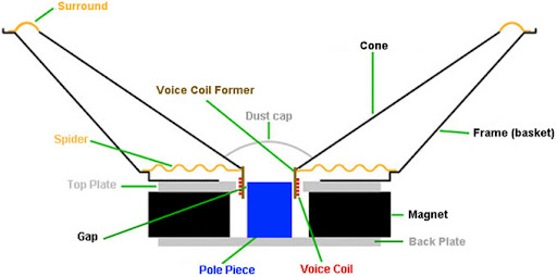
Picture: Loudspeaker diagram
These non-linearity’s happen because of the use of (Ferro) metals that bends the magnetic field. These metals (Pole Piece and Top Plate) are used to create the ‘gap’. The function of the gap is to canalise the magnetic field to its maximum strength. In this gap the voice coil moves forwards and backwards.

Picture: Modelled magnetic field
Non-linearity’s result in even harmonics (ears -> human and animal -> don’t like them). Some (old) people call it artificial distortion. In the picture the model shows clearly how the (Ferro) metal ‘bends’ the magnetic field around the voice coil. The waves you see represent the magnetic field off the same value.
Push-Pull:
Now, if you flip one driver (Push-Pull) and exchange the poles, both will move in similar direction (in-phase). The only difference is one cone moves forward and the cone of the flipped driver will move backwards.
That means that one driver moves into the non-linear area while the other driver moves in the linear area and visa versa. That’s how the distortion, produced by the non-linearity, is minimised.
Picture: Push-Pull
Push-Pull effect versus bandwidth:
The closer and symmetric the drivers are positioned the more effective the PP effect becomes and the wider the bandwidth of the push-pull effect becomes.
Push-Pull-Slot-Loaded:
The effects of the push-pull become maximised because both drivers load the same air molecules that are captured within the Slot (= Plenum). Because of this captured air the slot will make the system into a 6th order system.

Picture: PPSL
Also the pressure inside the Slot (= Plenum) will become much higher (forwards cone movement) and lower -> more negative (backwards cone movement) than when the drivers would load directly to the air in traditional push-pull setups. This pressure will suppress (damping) certain Partial Movements that result in even harmonics of the cone.
In a PPSL the two different drivers are no longer seen as independent systems like in a traditional Push-Pull setup. Instead they will be seen by the system as one. The advantage of that is improved phase & impulse figures.
Partial Movement:
Partial Movement is caused by the resonances of the materials and structure of the cone. (Additional note for TB46 😉 : this is caused by the “eigenfrequenz” of the cone). If you want to see models of Partial Movement from a cone use this LINK
Now lets hope I didn't make to many mistakes 😀
Last edited:
- Home
- Loudspeakers
- Subwoofers
- A Thread for those interested in PPSL enclosures