You can't easily use a passive crossover with a tapped horn. I've gone around and around with this using Akabak software. Unlike Hornresponse, Akabak has a means to simulate passive crossover components. The passive components mess up the electro-mechanical tuning of the tapped horn. The best route is to use an active crossover in front of the amplifier.
In addition, the T/S parameters for the MCM 8" are all over the place. They also change quite a bit after break-in. The suspension gets sloppy on these, so Cms changes a lot. To save you some trouble, give those MCM 8's a good break-in period and then measure the T/S parameters yourself. This will give your project the best chance for success.
In addition, the T/S parameters for the MCM 8" are all over the place. They also change quite a bit after break-in. The suspension gets sloppy on these, so Cms changes a lot. To save you some trouble, give those MCM 8's a good break-in period and then measure the T/S parameters yourself. This will give your project the best chance for success.
In addition, the T/S parameters for the MCM 8" are all over the place. They also change quite a bit after break-in. The suspension gets sloppy on these, so Cms changes a lot.
I second that motion... been there, done that. The best place for a MCM is a small sealed in car, or in a front loaded horn for PA with a very small sealed rear chamber. The small rear chamber helps control excursion, and consequently helps preserve the spider.
You want something that can hit 120db in car, you kinda need a 'car pa' style for your mcm's. In other words -- a PA FLH style cab with a sloping response, so in car it's flat.
my 2c.
Attachments
ok cool, so eq works just the same way as with sealed boxes. And when I add a coil, I'd also have to add the resistance.
Now that brings me to wonder, if I was to use a passive high pass filter - as with most of these bass horns a HP is needed - at say, 30Hz, would the caps and coils do anything unexpected to the response? Or would it just apply the designed high pass effect just the same way as it would if used on a sealed box?
That might be a stupid question with a simple answer, but I have to ask, since horns are sooooo different than a sealed box, and I have never used a horn before.
I have measured the effect of a series inductor on a Tang Band W6-1139 tapped horn. It does not behave exactly like a passive crossover per se.
The effect was nearly exactly what the model shows us, the peaks in the passband that correspond to the excursion minimas were damped somewhat, the saddle (excursion maxima) remained unchanged, except for the attenuation due to the additional series resistance.
You only need a single inductor, wire it in series with the drivers. As far as a high-pass, active is a much better idea, the coils and caps involved get rather unwieldy and extremely expensive if you want to have a slope that might actually protect your driver at the end of the day.
Last edited:
dang forgot littleMike.
You are probably 6'2" 240lbs Mike!
Mark
Close....6'1". You nailed the 240 part though....
While we're about the same size, Big Mike is a retired Marine. No one there was gonna call him "Old Mike", so he got "Big Mike". I got "Little Mike". My bosses are really creative when it comes to nicknames.
Problem is - we hired another Mike a while back....and he's littler than me - so what do we call him???

LOL
I was once in a class in high school where there were 4 Mark's. I was Gus!
I'm close 6', 206lbs lost a whack load since the spring. Never looked back since. Was 238. Happy at 206!
Do you have any actual measurements for the MCM 8" drivers? I would love to simulate using the correct specs. I might get me a bunch of them.
Mark
TS
Here's my effort - this is before break in.
How do they look?
1
* This data was exported from the Dayton Audio WT3 Woofer Tester
*
* Manufacturer:
* Model:
* Piston Diameter = 161.9 mm
* f(s)= 28.94 Hz
* R(e)= 3.38 Ohms
* Z(max)= 193.70 Ohms
* Q(ms)= 12.370
* Q(es)= 0.219
* Q(ts)= 0.216
* V(as)= 31.240 liters (1.103 cubic feet)
* L(e)= 2.67 mH
* n(0)= 0.33 %
* SPL= 87.27 1W/1m
* M(ms)= 57.64 grams
* C(ms)= 0.52 mm/N
* BL= 12.70
*
2
* Manufacturer:
* Model:
* Piston Diameter = 161.9 mm
* f(s)= 28.94 Hz
* R(e)= 3.33 Ohms
* Z(max)= 179.30 Ohms
* Q(ms)= 11.480
* Q(es)= 0.217
* Q(ts)= 0.213
* V(as)= 31.400 liters (1.109 cubic feet)
* L(e)= 2.63 mH
* n(0)= 0.33 %
* SPL= 87.34 1W/1m
* M(ms)= 57.36 grams
* C(ms)= 0.53 mm/N
* BL= 12.64
*
3
* Manufacturer:
* Model:
* Piston Diameter = 161.9 mm
* f(s)= 29.61 Hz
* R(e)= 3.31 Ohms
* Z(max)= 187.10 Ohms
* Q(ms)= 12.500
* Q(es)= 0.225
* Q(ts)= 0.221
* V(as)= 32.240 liters (1.139 cubic feet)
* L(e)= 2.63 mH
* n(0)= 0.35 %
* SPL= 87.60 1W/1m
* M(ms)= 53.36 grams
* C(ms)= 0.54 mm/N
* BL= 12.08
*
4
Manufacturer:
* Model:
* Piston Diameter = 161.9 mm
* f(s)= 29.61 Hz
* R(e)= 3.32 Ohms
* Z(max)= 179.90 Ohms
* Q(ms)= 11.550
* Q(es)= 0.217
* Q(ts)= 0.213
* V(as)= 32.300 liters (1.141 cubic feet)
* L(e)= 2.59 mH
* n(0)= 0.37 %
* SPL= 87.76 1W/1m
* M(ms)= 53.25 grams
* C(ms)= 0.54 mm/N
* BL= 12.31
*
*
You can't easily use a passive crossover with a tapped horn. I've gone around and around with this using Akabak software. Unlike Hornresponse, Akabak has a means to simulate passive crossover components. The passive components mess up the electro-mechanical tuning of the tapped horn. The best route is to use an active crossover in front of the amplifier.
Thats what I thought. now I know!
In addition, the T/S parameters for the MCM 8" are all over the place. They also change quite a bit after break-in. The suspension gets sloppy on these, so Cms changes a lot. To save you some trouble, give those MCM 8's a good break-in period and then measure the T/S parameters yourself. This will give your project the best chance for success.
I will post the break in measurements next week. Can i break them in by playing them on the floor in free air? Does it matter if the vent at the back is covered this way?
Jbell
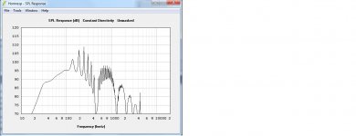
thx for the sim, I've added that to my hornresp collection to fiddle with
I have a few I made that has the same slope, but yours has much higher SPL. But my "bass corner" is at 30Hz instead. And THANK YOU for your encouragement on not giving up on eliminating the noise problem on the headunit (if you remember our discussion on the other thread) I finally opened the HU up, gone down to the PCB and bypassed a blown pico fuse. Not easy, but done. Now I can use my amps again, and have bass while I play with all these horn thingys
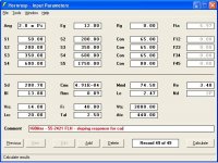
Because I now have power (RRRAAAAHHH!) and understand alot more what I should be looking for - I would like to start with a FLH with the w6-1139SI. Many TH has been done with this thing, I can only find 1 FLH - the insubnia FLH version by maxmercy. (later it turned into the arnachy TH). But at the minimum I'd need to refold it (to 7inches tall to make it as flat as possible)
Here is my try: (see attached) 2.83V, single w6-1139si, 45L, 30Hz.
The problem is that I don't know how to design the compression chamber. Any fast rules to help? Any existing designs that I missed?
Attachments
And THANK YOU for your encouragement on not giving up on eliminating the noise problem on the headunit (if you remember our discussion on the other thread) I finally opened the HU up, gone down to the PCB and bypassed a blown pico fuse. Not easy, but done. Now I can use my amps again, and have bass while I play with all these horn thingys
YEA -- good for you.... finding the 'right' answer... is always the right answer.
When breaking in new woofers I try not to block off the magnet vent. Whatever heat is generated, I want it to be able to get out. Thus far I've just propped them on edge and played the radio through them while I'm gone at work. After about 3 days of this the T/S parameters seem to settle for good. I give them enough power to get visable cone travel, but not enough to bottom out the voice coil.
- Status
- This old topic is closed. If you want to reopen this topic, contact a moderator using the "Report Post" button.
- Home
- Loudspeakers
- Subwoofers
- Can someone comment on my hornresp simulations on the MCM8?