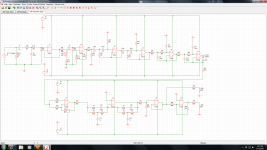
Hi could anyone please comment on the following circuit. Its an input filter + LR eq for a subwoofer. The LR values are not correct as I need to measure the driver in its box. The output are taken at R37 and R38 to be fed to two amps to work in bridge mode. In case there is anything wrong or that can be improved with the circuit please let me know. Thanks")
Attachments
I have been looking at your circuit today and pondering on the various design aspects. it has been awhile since I last built a crossover circuit.
What follows is a set of comments that come to mind.
Not everybody is going to agree with everything but lets get this party started!
R1 is not necessary.
C1 is quite small and could be increased to make sure that the passband is not effected.
RF input filter looks sensible.
The buffer into the gain control seems OK. I prefer a small value resistor (100R) in the feedback loop of a buffering op amp, apparently this helps the op amp recover from with any spikes which cause clipping.
C11 is probably not needed, Are R14 and R19 necessary? Re-arrange the filter stages so that one of the high pass filters is last in the filter chain, and this will block the majority of any accumilative DC offset.
I don,t really understand the circuit at IC X7?
What does R23 do?
Is the buffer at IC X9 necessary? Would IC X8 not drive the output? If the buffer IC X9 is desirable, then maybe the inverting output buffer X10 should be connected to the output of X8 to avoid going through an extra stage?
R32, R37 and R38 are not needed.
There is no decoupling shown on the op amp voltage rails. For optimum performance I would use some pairs of 100uf throughout the circuit depending on the physical layout, and local 0.1uF or 0.47uF decoupling caps as well.
Where one op-amp drives into the virtual earth of the next stage it is a good idea to add a decoupling capacitor right across both the voltage rails.
Hi Xoc thanks for the comments. With regards to your questions:
R1 is not necessary-Effectively thats debatable i have built xovers without it and things worked out well
C1 is quite small and could be increased to make sure that the passband is not effected-I will check it again but simulation shows its ok. The final sub will aim at 30Hz -3dB
RF input filter looks sensible. Cool
The buffer into the gain control seems OK. I prefer a small value resistor (100R) in the feedback loop of a buffering op amp, apparently this helps the op amp recover from with any spikes which cause clipping.I was not aware of that it won't hurt adding it
C11 is probably not needed-Its to avoid any crackles in the sound
Are R14 and R19 necessary? Re-arrange the filter stages so that one of the high pass filters is last in the filter chain, and this will block the majority of any accumilative DC offset-Great Suggestion will do that
I don,t really understand the circuit at IC X7? -Its a phase inverter i forgot to add the switch which connects the non-inverting input to ground
What does R23 do?-Basically ensure that the LR transform is fed properly.
Is the buffer at IC X9 necessary? Would IC X8 not drive the output? If the buffer IC X9 is desirable, then maybe the inverting output buffer X10 should be connected to the output of X8 to avoid going through an extra stage?
Well actualkly i don't mind as otherwise it would leave one opamp side unused so better use it.
R32, R37 and R38 are not needed.
R32 is essential here i would leave it as for R37 and R38 effectively i ave just left it there for simlation
There is no decoupling shown on the op amp voltage rails. For optimum performance I would use some pairs of 100uf throughout the circuit depending on the physical layout, and local 0.1uF or 0.47uF decoupling caps as well.Where one op-amp drives into the virtual earth of the next stage it is a good idea to add a decoupling capacitor right across both the voltage rails.
For usre i will use decoupling caps 0.1 uf at each opamp supply rail plus am planning on putting the reulators and smoothing caps on same board
I will re-adjust the schematics and post it again.
R1 is not necessary-Effectively thats debatable i have built xovers without it and things worked out well
C1 is quite small and could be increased to make sure that the passband is not effected-I will check it again but simulation shows its ok. The final sub will aim at 30Hz -3dB
RF input filter looks sensible.
Cool The buffer into the gain control seems OK. I prefer a small value resistor (100R) in the feedback loop of a buffering op amp, apparently this helps the op amp recover from with any spikes which cause clipping.I was not aware of that it won't hurt adding it
C11 is probably not needed-Its to avoid any crackles in the sound
Are R14 and R19 necessary? Re-arrange the filter stages so that one of the high pass filters is last in the filter chain, and this will block the majority of any accumilative DC offset-Great Suggestion will do that
I don,t really understand the circuit at IC X7? -Its a phase inverter i forgot to add the switch which connects the non-inverting input to ground
What does R23 do?-Basically ensure that the LR transform is fed properly.
Is the buffer at IC X9 necessary? Would IC X8 not drive the output? If the buffer IC X9 is desirable, then maybe the inverting output buffer X10 should be connected to the output of X8 to avoid going through an extra stage?
Well actualkly i don't mind as otherwise it would leave one opamp side unused so better use it.
R32, R37 and R38 are not needed.
R32 is essential here i would leave it as for R37 and R38 effectively i ave just left it there for simlation
There is no decoupling shown on the op amp voltage rails. For optimum performance I would use some pairs of 100uf throughout the circuit depending on the physical layout, and local 0.1uF or 0.47uF decoupling caps as well.Where one op-amp drives into the virtual earth of the next stage it is a good idea to add a decoupling capacitor right across both the voltage rails.
For usre i will use decoupling caps 0.1 uf at each opamp supply rail plus am planning on putting the reulators and smoothing caps on same board
I will re-adjust the schematics and post it again.
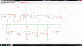
The 100R resistor on the output of the input buffer that drives the volume control is sensible (as the volume control is probably on a length of cable). But I dont think that it is necessary on IC,s X6 X7 & X8?
For example Linkwitz does not have these 100R resistors on his circuits.
Active Filters
The second 12db hi-pass filter should maybe be positioned before the bass boost circuit to ensure that the boost section has maximum headroom.
I don't see what X9 is adding to this circuit. You could always use a single op amp chip in one position to get an odd number of stages.
Hi Y'all,
Overall, looks good to me.
In additon to what has already been discussed:
I like to use a small capacitor accross the feedback resistor (e.g.: R17), something like a 10-30pF connected from output to inverting input, this is generally recommended when you're driving longer lines, or other capacitive loads. Also, the small damping resistor can be included in the feedback loop (unless it's only in the circuit to provide solder points for switch cables, etc.).
Sometimes, for decoupling of the power supply lines, a small resistor (22-47 Ohm) from power rail to IC power pin together with an electrolytic (10uF) paralleled w/ a small ceramic (.022-.1uF) close to the power pin can be helpful.
I have seen the suggestion to place the high-cut filter at the output, the rational being that all high frequency noise produced in the circuit will be attenuated. The final filter IC can drive the output just fine, you just need to add your inverter for the other output.
If you are planning a general purpose subwoofer card it would make sense to include a summing amplifier at the input as bjorno did in his example. For home theater use it might even be of interest to have four (or more) adjustable inputs.
It makes a lot of sense to add an adjustable phase control v. the simple inverting switch control.
bjorno: Do you have a source for the adjustable phase control you could share, and can you help with a circuit description? It looks interesting. On the summing amplifier: I don't generally like resistors that large for that purpose (noise?), I guess you are trying to keep the capacitors as small as possible.
Regards,
Overall, looks good to me.
In additon to what has already been discussed:
I like to use a small capacitor accross the feedback resistor (e.g.: R17), something like a 10-30pF connected from output to inverting input, this is generally recommended when you're driving longer lines, or other capacitive loads. Also, the small damping resistor can be included in the feedback loop (unless it's only in the circuit to provide solder points for switch cables, etc.
).Sometimes, for decoupling of the power supply lines, a small resistor (22-47 Ohm) from power rail to IC power pin together with an electrolytic (10uF) paralleled w/ a small ceramic (.022-.1uF) close to the power pin can be helpful.
I have seen the suggestion to place the high-cut filter at the output, the rational being that all high frequency noise produced in the circuit will be attenuated. The final filter IC can drive the output just fine, you just need to add your inverter for the other output.
If you are planning a general purpose subwoofer card it would make sense to include a summing amplifier at the input as bjorno did in his example. For home theater use it might even be of interest to have four (or more) adjustable inputs.
It makes a lot of sense to add an adjustable phase control v. the simple inverting switch control.
bjorno: Do you have a source for the adjustable phase control you could share, and can you help with a circuit description? It looks interesting. On the summing amplifier: I don't generally like resistors that large for that purpose (noise?), I guess you are trying to keep the capacitors as small as possible.
Regards,
Thanks for the replies
Hi thanks for the replies. I will have a look at the posted circuit tahnks a lot and for the variable phase too. Actually this is for a dedicated sub application to be driven by low level circuit thats why i did not include any attenuator for high level output.the frequency of the low pass is also fixed as the cross over point is from another active two way sealed loudspeaker thats already built with a -6dB point of 50 Hz .The filter board + amp and PSU will all be housed in the subwoofer back thats why i did not include anything to drive long lines. But your comments would be great in case i would sell the filter board as a general subwoofer filter board. I will start pcb layout soon and i will post the board layout here. As for bypass my personal choice would be to go for 100nF + 10uF at the opamp supply pins. In case you have further comments they are welcome
Hi thanks for the replies. I will have a look at the posted circuit tahnks a lot and for the variable phase too. Actually this is for a dedicated sub application to be driven by low level circuit thats why i did not include any attenuator for high level output.the frequency of the low pass is also fixed as the cross over point is from another active two way sealed loudspeaker thats already built with a -6dB point of 50 Hz .The filter board + amp and PSU will all be housed in the subwoofer back thats why i did not include anything to drive long lines. But your comments would be great in case i would sell the filter board as a general subwoofer filter board
. I will start pcb layout soon and i will post the board layout here. As for bypass my personal choice would be to go for 100nF + 10uF at the opamp supply pins. In case you have further comments they are welcomeYou might also be interested in this simpler 1-chip hi-passs filter with gain writeup
Just wondering, why: "...no longer recommended, the LR filter...",Nice work with all the VB6 calculators.
Thanks for the VB feedback..
After modelling both filters in winISD, I found that for my subwoofer needs, the extra complexity of the higher order filter was not needed. Just using a slightly higher design frequency gives enough excursion protection, with a very small amount of difference in output below that.
The filter linked to was developed with an eye to keeping it as simple as possible, whilst still providing protection and enough gain to do away with a cleanbox.
car subwoofer filter 48 db/octave
Hi could anyone please comment on the following circuit. Its an car subwoofer LP filter... tkx
Hi could anyone please comment on the following circuit. Its an car subwoofer LP filter... tkx
An externally hosted image should be here but it was not working when we last tested it.
car subwoofer filter 48 db/octave
Hi could anyone please comment on the following circuit. Its an input filter for a car subwoofer.
Hi could anyone please comment on the following circuit. Its an input filter for a car subwoofer.
An externally hosted image should be here but it was not working when we last tested it.
An externally hosted image should be here but it was not working when we last tested it.
- Status
- This old topic is closed. If you want to reopen this topic, contact a moderator using the "Report Post" button.
- Home
- Loudspeakers
- Subwoofers
- Subwoofer input+filter+eq circuit