Hi all,
I have a sub project with very little space available.
I have a 10" driver that I can squeeze in the space. The enclosure can be a cube around the speaker and a little more, but there is hardly any volume to talk about - probably as much as the speaker takes itself in all four corners combined. I want precise, not boomy sound for classical music, jazz and movies. It does not have to be very loud, although I know it (and the amp) has a potential to be. The room is very small, so there is no way to be physically more than 3m away from the sub.
Is it worth doing at all or should I go and look for 6" driver or something? What about this foam I have read about people put in smaller enclosures? What is the function of it, would it be recommended for my application and where do you obtain one?
Thank you for your time,
Edmunds
Hi all,
I have a sub project with very little space available.
I have a 10" driver that I can squeeze in the space. The enclosure can be a cube around the speaker and a little more, but there is hardly any volume to talk about - probably as much as the speaker takes itself in all four corners combined. I want precise, not boomy sound for classical music, jazz and movies. It does not have to be very loud, although I know it (and the amp) has a potential to be. The room is very small, so there is no way to be physically more than 3m away from the sub.
Is it worth doing at all or should I go and look for 6" driver or something? What about this foam I have read about people put in smaller enclosures? What is the function of it, would it be recommended for my application and where do you obtain one?
Thank you for your time,
Edmunds
Hi Edmunds,
Here is an idea :
b
")
Attachments
Thx, bjorno. Your post looks incredibly valuable, but also complex. Can you possibly spell it out?
I mean, I understand there is some kind of filter to compensate for the distortion the small box would cause, but can you explain what is the distortion exactly? What is the relation between the formulas on top for different enclosures and the circuit below. If I measure my enclosure to be 12L or 8L, how can I go to my resistor and capacitor values? What is the triangular component? Sorry for a dummy question ... And can you really come up with a circuit without knowing anything about the amp? How does that work and why?
Thank you, Chris661 for your reply - ported is not an option. There is just no space for ports, so I decided on closed early on. The amp is a dismantled Z5500. Based on TDA7294.
/Edmunds
I mean, I understand there is some kind of filter to compensate for the distortion the small box would cause, but can you explain what is the distortion exactly? What is the relation between the formulas on top for different enclosures and the circuit below. If I measure my enclosure to be 12L or 8L, how can I go to my resistor and capacitor values? What is the triangular component? Sorry for a dummy question
... And can you really come up with a circuit without knowing anything about the amp? How does that work and why?Thank you, Chris661 for your reply - ported is not an option. There is just no space for ports, so I decided on closed early on. The amp is a dismantled Z5500. Based on TDA7294.
/Edmunds
I have actually put it in a small box now and tried it out without the back properly sealed. I put it against the wall, some 1cm off it, but there is plenty of room for air to escape. It is still good sound from the total thing and the sub sounds ... well, ok. It is a bit lost in terms of precision - somehow it feels less accurate. I hope it will get better when I figure out how to seal it - the back is not square. It is also significantly less powerful than it used to be in the big box. On the edge of being too quiet, even if on the max sub output setting.
/Edmunds
/Edmunds
I crunched some numbers for you concerning your 10" driver....If you can get a sealed enclosure, stuffed with some Dacron or cotton batting(Pillow stuffing).......at a value of 1446 cubic inches....you will be right smack in the ballpark for achieving the best performance for this driver.
Try different dimensions to suit your space available...trying to hit that number of cu inches.
_______________________________________________________Rick.........
Try different dimensions to suit your space available...trying to hit that number of cu inches.
_______________________________________________________Rick.........
Here's a little information on the graphs Bjorno posted...
ESP - The Linkwitz Transform Circuit << this explains things pretty well...
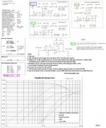
The red line is the correction curve applied by the Linkwitz Transform. The turquoise (green-blue) line is the sum of the circuits (there's an infrasonic filter to stop over-excursion at frequencies you'll never reproduce). Below the turquoise line, is the new response of the driver, after the correction has been applied. Bjorno selected ~35Hz as a lower cutoff. You could ask it to go lower, but you start running into serious problems with excursion when you turn it up. The next line down (green) is the high pass filter, which cuts off the really low stuff, and the last line is the bass response before any correction is applied.
Chris
ESP - The Linkwitz Transform Circuit << this explains things pretty well...
The red line is the correction curve applied by the Linkwitz Transform. The turquoise (green-blue) line is the sum of the circuits (there's an infrasonic filter to stop over-excursion at frequencies you'll never reproduce). Below the turquoise line, is the new response of the driver, after the correction has been applied. Bjorno selected ~35Hz as a lower cutoff. You could ask it to go lower, but you start running into serious problems with excursion when you turn it up. The next line down (green) is the high pass filter, which cuts off the really low stuff, and the last line is the bass response before any correction is applied.
Chris
Here's a little information on the graphs Bjorno posted...
ESP - The Linkwitz Transform Circuit << this explains things pretty well...
The red line is the correction curve applied by the Linkwitz Transform. The turquoise (green-blue) line is the sum of the circuits (there's an infrasonic filter to stop over-excursion at frequencies you'll never reproduce). Below the turquoise line, is the new response of the driver, after the correction has been applied. Bjorno selected ~35Hz as a lower cutoff. You could ask it to go lower, but you start running into serious problems with excursion when you turn it up. The next line down (green) is the high pass filter, which cuts off the really low stuff, and the last line is the bass response before any correction is applied.Chris
Thank you Cris for a perfect seconding of my simple picture: I've added two pictures that
_probably needs more explanations...b
Attachments
I guess the usage of two subs would put those figures to trash !!!
Not quite right:
b
Attachments
Thank you Cris for a perfect seconding of my simple picture: I've added two pictures that
b
Not a problem. I've used the same spreadsheet so I took plenty of time to ensure I know what I was doing.
The sims you've posted... I've never seen anything like it, but I could give it a go...
The yellow area is (I think) when the room enters "pressure mode", where the subwoofer pressurises the entire room equally, instead of sending waves around. This happens when the room size approaches (half?) wavelength of the frequency. Anyway, each of the different coloured lines correspond to a different position in the room, the positions and co-ordinates are shown (in metres, from the corner). If I had to choose one, I'd go for the green one, as there's no major peaks or dips there.
Following these sims (they only show how the room will interact - you have to combine them with a speaker response to see what's going to happen), I'd find a cabinet size that gives a fairly shallow roll-off (you could eq it to give a shallow roll-off if you desire), where the -3dB point is in the 60-70Hz range.
Of course, these simulations have their limitations - they only show the result of the bare room. Adding a sofa or other furnature is likely to improve results, as it's not all reflective surfaces.
Chris
Hmm.
I think, after much reading, I might start to actually understand something here. One thing I cannot find a decent answer to is roll-off. What exactly does it mean? And why is it important/significant?
Also, I am reading in other forums, my amp has a crossover for the sub at around 120Hz (is there a way to tell that apart from consulting the manufacturer, btw?). I understand the crossover point is kind of where the sub takes over from the main speakers and the other way around. That would be my upper limit for the sub, then?
In the excel spreadsheet from linkwitz, graphs project frequencies up to 300Hz or so. Shall I just ignore this and concentrate on, say, 25-120Hz range or is there a way to set the top limit somehow and that would alter the curves and thus, resistor and capacitor values for the filter?
Shall I maybe just build/buy, say, 8 channel EQ and adjust as I hear it? Would it work with the crossover thing above?
Thank you for your time,
Edmunds
I think, after much reading, I might start to actually understand something here
. One thing I cannot find a decent answer to is roll-off. What exactly does it mean? And why is it important/significant?Also, I am reading in other forums, my amp has a crossover for the sub at around 120Hz (is there a way to tell that apart from consulting the manufacturer, btw?). I understand the crossover point is kind of where the sub takes over from the main speakers and the other way around. That would be my upper limit for the sub, then?
In the excel spreadsheet from linkwitz, graphs project frequencies up to 300Hz or so. Shall I just ignore this and concentrate on, say, 25-120Hz range or is there a way to set the top limit somehow and that would alter the curves and thus, resistor and capacitor values for the filter?
Shall I maybe just build/buy, say, 8 channel EQ and adjust as I hear it? Would it work with the crossover thing above?
Thank you for your time,
Edmunds
(sub)woofers have a natural roll-off at high frequencies because of their diameter which is related to the wavelength reproduced ,and also the mechanical and electrical parts ( coil) are designed to behave like a piston .
If displacement of air for a targeted SPL is not reached with diameter ,or better ,cone surface area ,then excursion provides it . This means more power thrown into it and more heat production . That's why in a sealed box excursion
may be limited by the air-spring effect and power ...Ok Power :
Take a look at Sunfire products ....
The low-pass freq of subwoofers is usually set below 100 Hz ,the lower the better for perfect integration with the satellites . Don't need no graphic or PEQ
because what's in a dedicated sub amplifier is ok : freq cut ;phase (should be continuous or with many steps from -180° to +180° ,then just invert the phase of the cables );level .
picowallspeaker - sorry, but it is not much I get from your post. it can be my english.
It is a known fact there is a crossover circuit for the sub in the amp already, that limits the frequencies flowing to the sub in 35 to 150Hz range. I know this is high for many subs, but that is a given in my case - the sub has to make up for single driver small satellites.
I take from the spreadsheets, the linkwitz circuit is kind of more than just a filter/equalizer - the basic idea is, it let's you compensate for the properties of the enclosure, so my take is, it will improve things even if I connect the circuit after the built-in crossover, as the crossover was built for "standard" enclosure and mine is hardly an enclosure at all (useful volume is about 8L, which I'm about to stuff with pillow material, for a 10" driver).
Is my thinking correct?
/Edmunds
No ,it's my english ! Also technicality ,maybe ,as I've never done a powerful sub . But math is right : to obtain a certain MOL in a closed box ,excursion matters . And excursion is given by power ,lots of . An issue is that it brings heat ,so thermal capacity of the speaker has to be taken into account . The driver you have has enough Bl to react to Back EMF given by the little volume.
Little volume helps sensitivity above resonance frequency ,below it, it's a matter of power . And i forgot the High Pass that is usually included in a sub woofer amp ,which limits excursion of course ,and maximizes efficiency in the given bandwidth .
So your feeling of having a "so-so.." sub may be only dictated by the lack of power and control from the amp .
How about using a 3rd order closed box. By having a capacitor in line with the woofer you can built the box up to a Qb of 1 or 1.1 and equalize it with the capacitor.
I have been thinking of doing this myself with a pair of Dynaudio 30W100 woofers I have laying around.
Regards,
Hjalmar Dijkstra
I have been thinking of doing this myself with a pair of Dynaudio 30W100 woofers I have laying around.
Regards,
Hjalmar Dijkstra
How about using a 3rd order closed box. By having a capacitor in line with the woofer you can built the box up to a Qb of 1 or 1.1 and equalize it with the capacitor.
I have been thinking of doing this myself with a pair of Dynaudio 30W100 woofers I have laying around.
Regards,
Hjalmar Dijkstra
Yes, that method would work with the Tangband driver(Qm~10): but
not well with the Dynaudio due to it's very low Qm(=~2.7), if not pushed upwards with added mass. IMO, its not worth to loose driver sensitivity and SQ with this method.b
Yes, that method would work with the Tangband driver(Qm~10): but
b
Can you please explain the influence of Qm on a 3rd order in-line capacitor design? In the articles I have read about I could not find any limitations due to the Qm.
Thanks in advance,
Hjalmar Dijkstra
- Status
- This old topic is closed. If you want to reopen this topic, contact a moderator using the "Report Post" button.
- Home
- Loudspeakers
- Subwoofers
- Sub in a small enclosure