Hi,
Interesting stuff Brian, I think we're all waiting for your high SPL results.
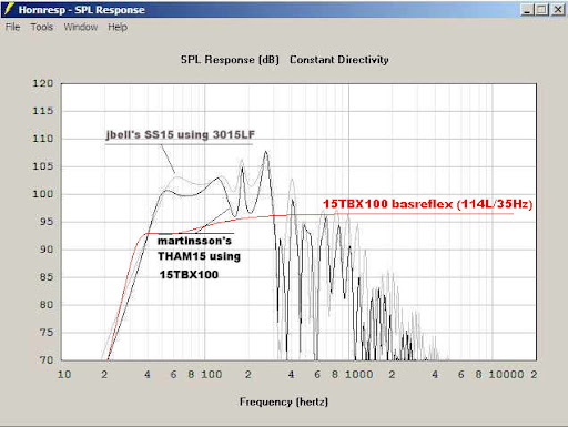
As an aside, I compared the THAM15 to the SS15:
Regards,
Not surprising - isn't the SS15 a larger box? If we can successfully deal with the notch in the THAM15's response though, the result would be something with a wider passband and lower cutoff frequency.
Question: how do these compare to a simple vented box using the same driver?
You may want to build your own THAM15 model from the plans.As an aside, I compared the THAM15 to the SS15:
It should look something like this with 2.83v:
Xco1's model on the first page is pretty close. L34 is a little long, do to his measuring a right corner at the end. You want to measure without the line through the corner, and then place the area line to account for the volume in AkAbak.
Last edited:
Question: how do these compare to a simple vented box using the same driver?
Hi guys,
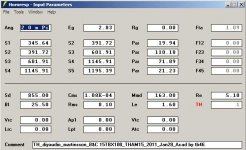
I did build my own ACAD model, and arrived my Hornresp Input data from there. I even used soho54's corner method. I also started with an overlay on Xco1's nice drawing. For general comparison, and future development I used the 4-section model. Let me know if you see any mistakes.
I agree on the internal volumes: according to Hornresp using Par for both models: THAM15=149.7 Litres / SS15=209.757 Litres. I've designed quite a few folds for the 15TBX100 that don't have the big notch. I think it is mainly a matter of increasing L45 and S4/S5, and go with a slightly larger volume (about 190 ltr, or so).
Regards,
Attachments
It is jam up except for the S3 point. You just picked the wrong spot. If you take your model, and unfold it you will see the S3 point should be at the last bend. Right before it is a large section with zero flare around the 180deg turn, and then a constriction followed by a large increase in volume over a short distance. You have too much volume in the 3rd quarter of the horn, before the tap to model the real horn.
The total length, and horn section area numbers are spot on though, and very close to what I got from my own model.")
I don't have the THAM SketchUp here, but this should show what I mean.
These two pics illustrate the base issue. It is reversed here, but I think you will get the idea. I don't have time to draw up new gifs right now.
The second one is more correct. If you kept moving to the left you would start to get extra volume on the right side of the selection point.
This picture will show how I go about it. Using the Spud here.
You can eyeball it in the Xoc1 straight horn illustration. You just have to remember his third section is to long.
The dip in the finished THAM15 is a fold translation error. HR can't quite sim it perfectly because of the non flared section. You need one more segment to completely capture it. As such the second peak(3rd Harmonic) is a little overstated, and the first peak(1st Harmonic) is a little under stated. AkAbak handles things much better here.
EDIT: also, you don't want to use the supplied BL or Mms as Mmd. Let HR calculate those for you. It makes a big difference sometimes.
The total length, and horn section area numbers are spot on though, and very close to what I got from my own model.
I don't have the THAM SketchUp here, but this should show what I mean.
These two pics illustrate the base issue. It is reversed here, but I think you will get the idea. I don't have time to draw up new gifs right now.
The second one is more correct. If you kept moving to the left you would start to get extra volume on the right side of the selection point.
This picture will show how I go about it. Using the Spud here.
You can eyeball it in the Xoc1 straight horn illustration. You just have to remember his third section is to long.
The dip in the finished THAM15 is a fold translation error. HR can't quite sim it perfectly because of the non flared section. You need one more segment to completely capture it. As such the second peak(3rd Harmonic) is a little overstated, and the first peak(1st Harmonic) is a little under stated. AkAbak handles things much better here.
EDIT: also, you don't want to use the supplied BL or Mms as Mmd. Let HR calculate those for you. It makes a big difference sometimes.
Last edited:
It should look more like the purple line here.
Also in the previous graphs I posted, they were at 2.43v not 2.83v. I typo'ed the voltage when I changed them from my default 1w/1m numbers. It should also be 5ohm minima, 6ohm would be the rated spec.
I should stop posting from abroad.
Also in the previous graphs I posted, they were at 2.43v not 2.83v. I typo'ed the voltage when I changed them from my default 1w/1m numbers. It should also be 5ohm minima, 6ohm would be the rated spec.
I should stop posting from abroad.
Last edited:
THAM15 vs 60l vented sub
Both with 2.83v in
Both a 6ohm minima load
Nice. The sim of the vented output might be a bit optimistic though, considering that HornResp does not include the effect of losses. Still, it shows what looks like about 2.5dB of gain across the passband.
Hi soho54,
Thanks for the analysis, I'll have to chew on that one a bit, but that's why I'm here.
Let me just think out loud: the way I picked the S3 point, is that it is a relatively clean horn section from S2 to my S3 with only minor (90 degree) bends at a relatively squashed cross-section. I can visualize what is acoustically happening in that section. The following two bends (from my S3 to S4) are roughly 180 degrees each, and I find it hard to see how they can be modelled short of a full FEA analysis, but I admit, I have to use AkAbak more. The way I understand what Tom Danley has said about the corners and bends: it is important to keep the volume about the same as the horn would have, if it were the same length (as the centerline?) for the given hron tapers (surrounding?: before and after the bends); (this is my interpretation, from memory, as I cannot find the respective TD comment).
I like your interpretation of the SPUD, but I still feel you should be able to place the S3 point anywhere between S2 and S4, and arrive at approximately the same response. I just don't like to pick a point in the middle of a bend for any of the definition points, unless it is unavoidable. Luckily the wavelength below 100Hz are so long, that they just flow over a lot of errors. One of the differences may the use of Par v. Exp.
As to the supply voltage and conditions, I just use 2.83V and 2pi for comparison. Modern amplifiers being what they are.
Thanks again, input, I need input.....
Regards,
Thanks for the analysis, I'll have to chew on that one a bit
, but that's why I'm here.Let me just think out loud: the way I picked the S3 point, is that it is a relatively clean horn section from S2 to my S3 with only minor (90 degree) bends at a relatively squashed cross-section. I can visualize what is acoustically happening in that section. The following two bends (from my S3 to S4) are roughly 180 degrees each, and I find it hard to see how they can be modelled short of a full FEA analysis, but I admit, I have to use AkAbak more. The way I understand what Tom Danley has said about the corners and bends: it is important to keep the volume about the same as the horn would have, if it were the same length (as the centerline?) for the given hron tapers (surrounding?: before and after the bends); (this is my interpretation, from memory, as I cannot find the respective TD comment).
I like your interpretation of the SPUD, but I still feel you should be able to place the S3 point anywhere between S2 and S4, and arrive at approximately the same response. I just don't like to pick a point in the middle of a bend for any of the definition points, unless it is unavoidable. Luckily the wavelength below 100Hz are so long, that they just flow over a lot of errors. One of the differences may the use of Par v. Exp.
As to the supply voltage and conditions, I just use 2.83V and 2pi for comparison. Modern amplifiers being what they are.
Thanks again, input, I need input.....
Regards,
Last edited:
Interesting stuff Brian, I think we're all waiting for your high SPL results.
Gotta wait a little longer - the neighbours seem to be back
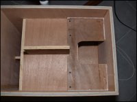
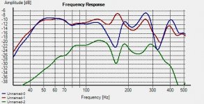
.After some more fiddling around, I settled for the simplest "fix" possible - a piece of board across the 3rd fold that cut the cross-section at that point by 2/3rds. I've included an image of the change below, along with the measured frequency response before (blue) and after (red) the change. In green is the response measured at the point - I noticed that it measured fairly flat before the addition of the extra panel, and the notch appeared after the addition. All responses are 1/6th octave smoothed. Most definitely the extra panel changes the response at that location. Perhaps taking measurements at that location could help to fine-tune the modification.
There's an audible difference before and after adding the "dogfood duct". Whether or not that difference remains audible once the TH is used as part of a full-range system remains to be seen.
Concerning SPL and compression measurements, as I mentioned the neighbours are back, so hooking it up to the car amp to give it a good 100W or so was out of the question. However, I did do some testing in-house and it seems to remain quite linear up to the output capabilities of my (admittedly small) temporary amp I'm using at the moment. Basically I used HolmImpulse to measure the FR and stepped the output level up by 10dB per step, and set HolmImpulse to auto-adjust to 0dB. My thinking was, if the resulting graphs overlay each other perfectly, then compression is basically non-existent, and they did up to the limits of my amp.
If the neighbours are out tomorrow, I'll repeat the test using my car amp, which should add about 6dB of output capability.
Attachments
Hi Brian,
The is just a lot more going on in these bends, than what initially meets the eye.
Regards,
I think it's just coincidence that the notch "fix" ended up being at that point where the bend starts. All to do with the way the horn is folded, rather than anything to do with the bend itself.
A similar "fix" for my TP POC#1 ended up nowhere near one of the bends.
Hmm... Now that I've dealt with the dip, I wonder if there's a way to deal with the peak at 160 or so Hz...
The bends are made out to be harder than they are. The quote you are talking about from Tom is where he is explaining how to convert a straight horn simulation into a folded horn, and how it can be messed up during the translation, IIRC. The idea is to carry the horn around the bend like you were just bending it around. You want to keep the volume, distance, and flare rate correct at every position around the bend. You are going to get a little extra volume around the corner if no filler is used, and it will be ok as long as it is kept to a minimum. Calculate the volume that was supposed to be in the straight horn section that is taken up with the bend, and then calculate the actual volume taken up. They should be pretty close. If not you will want to redo the bend, or come up with a new simulation. Any mess up will throw your sim out the window, as has happened here it seems.Let me just think out loud: the way I picked the S3 point, is that it is a relatively clean horn section from S2 to my S3 with only minor (90 degree) bends at a relatively squashed cross-section. I can visualize what is acoustically happening in that section. The following two bends (from my S3 to S4) are roughly 180 degrees each, and I find it hard to see how they can be modelled short of a full FEA analysis, but I admit, I have to use AkAbak more. The way I understand what Tom Danley has said about the corners and bends: it is important to keep the volume about the same as the horn would have, if it were the same length (as the centerline?) for the given hron tapers (surrounding?: before and after the bends); (this is my interpretation, from memory, as I cannot find the respective TD comment).
I have a thread showing how I am tackling it right now, and it shows what I mean.
Horn Folding in Sketch-Up - AVS Forum
Most designs out there mess this portion up using cut and twist 90deg methods of bending. This normally results in a non-flared, overly flared, or pinch point in the bend.
It doesn't work out that way. In the SPUD example, if you look close you will see a straight line running from the top of S2 to S4. S3 is the point of the PAR sectioned horn that is the greatest distance from the straight line. When you place S3 there you pull the line down to that point, and the volume match between the second and third sections will be as close to accurate as possible. If you put the S3 (green line) point too early the volume up to S3 will be OK but the third section will now have to much volume, and the sim is wrong. If you put the S3 point to far down the line, to the right your third section volume will be good, but there is now extra volume in the second section, and your sim is off.I like your interpretation of the SPUD, but I still feel you should be able to place the S3 point anywhere between S2 and S4, and arrive at approximately the same response.
The only time you can pick a random point as S3 is when the horn is truly a single flare rate. This would be a 3 section horn designed in HR with an Auto S2 & S3, if being built circular that means Con, and if it is going to be square it means using Par.
Nah, the flare function used doesn't matter. The example is shown as extreme as possible to get the point across. Even in this example if you are using at least 3 flare segments it doesn't matter if you chose Con, Par, or Exp as they will all sim the same way.One of the differences may the use of Par v. Exp.
This is a link to the original post the pics came from. Click Me!!
I keep meaning to write something up on flare rates to add to the Hornresp How To, but keep putting it off.
Last edited:
I've included an image of the change below, along with the measured frequency response before (blue) and after (red) the change. In green is the response measured at the point - I noticed that it measured fairly flat before the addition of the extra panel, and the notch appeared after the addition.
...and here is the impedance response, before (blue) and after (red) the addition of the duct. Looks like Fb shifted down from around 42.7 Hz to 39 Hz, and there's an additional "ripple" at 170 Hz, where the new peak in the FR is located.
Attachments
Good to see the FC drop, and tale-tale Impedance wiggle.
I have been thinking about it, and using a single board should make it easier to check for compression in AkAbak. The pressure, and velocity numbers can be checked for the restricting "duct," and it could be as simple as checking a port's diameter out.
I think it would be better to design the horn without the dip in the first place, but should boo boos happen, it's an easier fix than starting a new fold. Assuming you can get to the area in question, and can use AkAbak.
Last edited:
I have been thinking about it, and using a single board should make it easier to check for compression in AkAbak. The pressure, and velocity numbers can be checked for the restricting "duct," and it could be as simple as checking a port's diameter out.
Cool - it would be interesting to see what AkAbak suggests. This duct is partway down the horn rather than venting to the outside, so I suspect that the compression might not be as bad as we think it might be. Note: I did try it on bend #2 - just made the notch even bigger. Its effect is definitely very location-dependent.
I think it would be better to design the horn without the dip in the first place, but should boo boos happen, it's an easier fix than starting a new fold. Assuming you can get to the area in question, and can use AkAbak.
In the case of the THAM15, I think it was designed knowing that a notch would present itself in the upper part of the FR - it appears to be designed primarily with the intent of keeping box size low AND getting a lower cutoff point. It's the same decision I took with POC#2 - with the FR notch predicted to occur outside of the target passband, I wasn't too bothered with it. Now, with the possibility of reducing or eliminating the notch with a simple modification to the horn, well, maybe I'll get to eat my cake and have it too
.Give me some time, and I'll see what I can do. I'll have to find my model, and alter the path lengths a little to use the new duct section. I think it is on my main computer, and it won't be back online until Monday. I think I may have posted it up in your thread, so we may be in luck.
The way I took the THAM15 discussion here was that the first sim (in the first post here) was done, and it only shows a ~5-6dB dip. The measured response shows the dip to be much worse. It then turns into the "HR doesn't do whatever right, so the only way to know is to build" argument. When in fact it is the normal case of the sim and real build not complementing one another.
The way I took the THAM15 discussion here was that the first sim (in the first post here) was done, and it only shows a ~5-6dB dip. The measured response shows the dip to be much worse. It then turns into the "HR doesn't do whatever right, so the only way to know is to build" argument. When in fact it is the normal case of the sim and real build not complementing one another.
Here is the simplest way to do it. If I can find a simple AcouResistance calculation it could be added into the AcouMass element, but I don't have a simple on right now. As it stands now you can just add a duct to calculate the AcouResistance for you, and then just add the AcouMass afterward.Cool - it would be interesting to see what AkAbak suggests.
AcouMass calculation shown in script.
Remember my model was based on an earlier version of your spreadsheet, so there is a slight difference between what it models, and what was built. It still works out great here.
Code:
System 'DEMO1'

Def_Driver 'Driver'
dD=26cm dD1=11cm tD1=6.5cm |Cone
t1=1.1cm
fs=39Hz Vas=92L Qms=7.5
Qes=0.31 Re=5.2ohm Le=0.37mH ExpoLe=0.618


Def_Const
{
S1 = 4.8e-2;
S2 = 6.3e-2;
S3 = 8.2e-2;
S4 = 9.6e-2;
S5 = 10.9e-2;
S6 = 10.1e-2;
S7 = 10.1e-2;
S8 = 11.8e-2;
S9 = 13.1e-2;
S10 = 12.1e-2;
S11 = 12.1e-2;
S12 = 14.5e-2;
S13 = 17.1e-2;
S14 = 16.1e-2;
S15 = 17.3e-2;
S16 = 15.8e-2;
S17 = 13.6e-2;
S18 = 13.6e-2;
S19 = 14.8e-2;
S20 = 13.4e-2;
S21 = 11.8e-2;
S22 = 13.6e-2;
S23 = 16.3e-2;
S24 = 15.3e-2;
S25 = 16.3e-2;
S26 = 17.7e-2;


L1 = 20e-2;
L2 = 26.7e-2;
L3 = 2.5e-2;
L4 = 3.3e-2;
L5 = 2.0e-2;
L6 = 33.0e-2;
L7 = 3.0e-2;
L8 = 3.9e-2;
L9 = 2.5e-2;
L10 = 30.5e-2;
L11 = 4.0e-2;
L12 = 5.2e-2;
L13 = 2.85e-2;  |was 3.7
L14 = 3.15e-2;  |was 4.0
L15 = 5.4e-2;
L16 = 4.0e-2;
L17 = 17.0e-2;
L18 = 3.0e-2;
L19 = 4.7e-2;
L20 = 4.0e-2;
L21 = 4.2e-2;
L22 = 4.8e-2;
L23 = 3.4e-2;
L24 = 13.9e-2;
L25 = 20.9e-2;
}


Driver Def='Driver''Driver'
Node=1=0=100=3


Waveguide 'Horn segment 1'
Node=3=2
WTh=41.4cm HTh={S1}
WMo=41.4cm HMo={S2}
Len={L1}

Waveguide 'Horn segment 2'
Node=3=4
WTh=41.4cm HTh={S2}
WMo=41.4cm HMo={S3}
Len={L2}

Waveguide 'Horn segment 3'
Node=4=5
WTh=41.4cm HTh={S3}
WMo=41.4cm HMo={S4}
Len={L3}

Waveguide 'Horn segment 4'
Node=5=6
WTh=41.4cm HTh={S4}
WMo=41.4cm HMo={S5}
Len={L4}

Waveguide 'Horn segment 5'
Node=7=6
WTh=41.4cm HTh={S6}
WMo=41.4cm HMo={S5}
Len={L5}

Duct 'Duct segment 6'
Node=7=8
WD=41.4cm HD={S6} Len={L6}

Waveguide 'Horn segment 7'
Node=8=9
WTh=41.4cm HTh={S7}
WMo=41.4cm HMo={S8}
Len={L7}

Waveguide 'Horn segment 8'
Node=9=10
WTh=41.4cm HTh={S8}
WMo=41.4cm HMo={S9}
Len={L8}

Waveguide 'Horn segment 9'
Node=11=10
WTh=41.4cm HTh={S10}
WMo=41.4cm HMo={S9}
Len={L9}

Duct 'Duct segment 10'
Node=11=12
WD=41.4cm HD={S10} Len={L10}

Waveguide 'Horn segment 11'
Node=12=13
WTh=41.4cm HTh={S11}
WMo=41.4cm HMo={S12}
Len={L11}

Waveguide 'Horn segment 12'
Node=13=14
WTh=41.4cm HTh={S12}
WMo=41.4cm HMo={S13}
Len={L12}

Waveguide 'Horn segment 13'
Node=50=14
WTh=41.4cm HTh={S14}
WMo=41.4cm HMo={S13}
Len={L13}


Duct 'Duct segment DogFood'
Node=51=52
WD=13.8cm HD={S14} Len=1.7cm

AcouMass    'Ma1'
Node=50=51
Ma=7.13kg/m4  |(1.2/((Dogfood SQRT(Sd/Pi)*2))* 100


Waveguide 'Horn segment 14'
Node=52=16
WTh=41.4cm HTh={S14}
WMo=41.4cm HMo={S15}
Len={L14}

Waveguide 'Horn segment 15'
Node=17=16
WTh=41.4cm HTh={S16}
WMo=41.4cm HMo={S15}
Len={L15}

Waveguide 'Horn segment 16'
Node=18=17
WTh=41.4cm HTh={S17}
WMo=41.4cm HMo={S16}
Len={L16}

Duct 'Duct segment 17'
Node=18=19
WD=41.4cm HD={S17} Len={L17}

Waveguide 'Horn segment 18'
Node=19=20
WTh=41.4cm HTh={S18}
WMo=41.4cm HMo={S19}
Len={L18}

Waveguide 'Horn segment 19'
Node=21=20
WTh=41.4cm HTh={S20}
WMo=41.4cm HMo={S19}
Len={L19}

Waveguide 'Horn segment 20'
Node=21=22
WTh=41.4cm HTh={S21}
WMo=41.4cm HMo={S20}
Len={L20}

Waveguide 'Horn segment 21'
Node=22=23
WTh=41.4cm HTh={S21}
WMo=41.4cm HMo={S22}
Len={L21}

Waveguide 'Horn segment 22'
Node=23=24
WTh=41.4cm HTh={S22}
WMo=41.4cm HMo={S23}
Len={L22}

Waveguide 'Horn segment 23'
Node=25=24
WTh=41.4cm HTh={S24}
WMo=41.4cm HMo={S23}
Len={L23}

Waveguide 'Horn segment 24'
Node=25=26
WTh=41.4cm HTh={S24}
WMo=41.4cm HMo={S25}
Len={L24}

Waveguide 'Horn segment 25'
Node=26=27
WTh=41.4cm HTh={S25}
WMo=41.4cm HMo={S26}
Len={L25}

Duct 'Du1' Node=100=26
WD=41.4cm HD=30cm Len=1.7cm

Radiator 'Horn mouth' Def='Horn segment 25'
Node=27
Attachments
Last edited by a moderator:
That should be Ma=7.13kg/m4 |(1.2/((Dogfood SQRT(Sd/Pi)*2))*100 in the script.
Meaning the dogfood restriction plate opening's Sd. It is used to get a circular diameter number needed here. It's late.
I sent a PM to the Admin, so maybe it will get fixed in the previous post.
Meaning the dogfood restriction plate opening's Sd. It is used to get a circular diameter number needed here. It's late.
I sent a PM to the Admin, so maybe it will get fixed in the previous post.
- Home
- Loudspeakers
- Subwoofers
- THAM15 - a compact 15" tapped horn