you missed seeing the measurement on the side of the pipe.
And no, I did not miss the point. I do large room acoustics. You can deal acoustically with a wave with:
1. absorption. (like the 1/2" foam used in the spud knock off that DOES NOT have an acoustic absorption peak where the dip showed up in that testing, meaning that extra foam did not cause an non uniform reduction in spl.)
2. tuned cavity. (like the helmholtz in the dts-20, that tom obviously designed with tall peaks and a deep valley between them, and then used a combination of the helmholtz/inductor to flatten that out.)
3. oblique reflection/diffusion. (like the reflectors that I have installed and measured in the MANY tapped horns that I have built.)
All three work in room, and all three work in cabinet.
Here's a thought for you... (hey actually putting my music degree to work here....)
A clarinet is a quasi closed ended pipe 1/4 wave resonator. Think about a clarinet here.... then think about the shape of a typical tapped horn.
I know a clarinet is a quasi closed ended pipe, as it has no even order harmonics in the lower register. It resonates at 1/4 wave. (yes, you guessed it, I'm a wind player)
I'll submit a guess that the sections of a TH behave like a clarinet and are actually 1/4wave resonators due to the pressure coming from the 'throat side' of the driver, and that the reflectors actually disrupt that segment from acting like a 1/4 wave device.
So, see if I got your theory right Brian…
The reflectors seem to work fine as an optimiser for the expansion problems in the bends (and the name should be changed in volume optimizers).
As a soundwave reflector (for preventing ¼ wave cancellations) they have almost no use cause then they need to have the surface for ½ wavelengths (following your rules of room acoustics).
This is what you try to say, right?
Hi Y'all,
1/4 tube are not Helmholz resonators, and they work differently:
From diyaudio Tom Danley's TOWER OF POWER, Post #128: "...Helmholtz resonators are phase inverters, produce a 180 degree phase shift between the driving pressure and output pressure. A quarter wave resonator, the lowest mode of such a thing, only has a 90 degree phase shift I / O. ..."
Regards,
Hi Y'all,
1/4 tube are not Helmholz resonators, and they work differently:
From diyaudio Tom Danley's TOWER OF POWER, Post #128: "...Helmholtz resonators are phase inverters, produce a 180 degree phase shift between the driving pressure and output pressure. A quarter wave resonator, the lowest mode of such a thing, only has a 90 degree phase shift I / O. ..."
Regards,
yep, you are right oliver -- my bad for calling them helmholtz... I should say 1/4wave resonator. (you always seem to catch my goof ups, thank you.)
And that also goes with Tom's statement about the 'limited' amout of phase shift within a TH cabinet vs a ported cabinet, that I quoted earlier.
(back to that clarinet example)
Last edited:
Speaking generically, it isn't the bends, it is the material the horn is made out of. Everything in the HR simulation assumes absolute values, or think of it as infinity hard surfaces. Anything striking the surface is reflected at the same amplitude.Simming the TH as shown in the schematic, peaks are evident at 160 and 230Hz. The "Q" of these peaks is very narrow. When the TH is folded, you will no longer have a single, unique path thru the horn, and the "Q" of these peaks will be wider and the peaks will be much lower.
Or am I wrong ...
This is what produces the high sharp peaks and dips in all the HR graphs, FR, displacement, impedance... When you build the horn in real like actual materials do not work this way, and small amounts of energy are transferred in several different ways. When you go to measure the real horn (let's keep it a straight perfect copy for now,) the peaks and dips will be there, but they will not have the same absolute amplitude in gain or loss.
Bends alter the horns expansion rate, volume, and air resistance in the immediate area. Depending on the horn and it's properties slight variations can cause drastic changes to the peak/null, and random overal amplitudes in certain locations along the horn.
85Hznow, if this pipe is 31 3/4" long, making the total length of pipe around 40" or so, and closed end pipes are 1/4 wave resonators -- what is the fundamental of that 1/4 wave resonator? possibly around 80hz?
The 1/4W resonators are not for the FR peaks. The are to dampen the harmonic content from other frequencies that get boosted by the horn. Let's say the horn has a peak at 80Hz. You can add EQ to lower this peak, but that only effects that one frequency. Now you have a real driver playing a 20Hz tone loud enough to distort. The 2nd harmonic distortion is now being boosted to higher levels by the horns natural peak at 80Hz, and there is nothing you can normally do about it. Enter the 1/4W resonators.I know ivan is quoted as saying it was for 'distortion' reasons, and that closed pipes only resonate on the fundamental and odd order harmonics...
still I personally believe that the 2 pipes are set for fundamentals of the 2 normal peaks of a TH to tame them down, and the inductor is there to fill in the gap. As a side bonus, you also get reduction in 3rd order harmonics of the 2 'peaks' of a typical TH.
meaning, the helmholtz is there to tame a resonance that is IN BAND.... which was my point.
TH's are 1/4WL resonators, closed end air columns. Most all bass horns are at the cutoff.A clarinet is a quasi closed ended pipe 1/4 wave resonator. Think about a clarinet here.... then think about the shape of a typical tapped horn.
I know a clarinet is a quasi closed ended pipe, as it has no even order harmonics in the lower register. It resonates at 1/4 wave. (yes, you guessed it, I'm a wind player)
I'll submit a guess that the sections of a TH behave like a clarinet and are actually 1/4wave resonators due to the pressure coming from the 'throat side' of the driver, and that the reflectors actually disrupt that segment from acting like a 1/4 wave device.
") That is how they work, it's no secret. Have you done any kind of research into this subject? The section folds in a TH are not closed end air columns. They would be open end air columns, and work in 1/2WL modes if anything.
That is how they work, it's no secret. Have you done any kind of research into this subject? The section folds in a TH are not closed end air columns. They would be open end air columns, and work in 1/2WL modes if anything.
Last edited:
Jbell, thanks for the sharing, oh and Brian you can use your tube you already build, seems a perfect candidate…
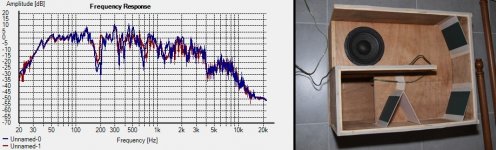
I've done some tests tonight, using matt-board taped into the corners to simulate reflectors. I took great pains (ok, maybe not so great) to ensure everything else remained constant, so the measured FR changes will in the main be caused by the insertion of the reflectors. Are you interested in seeing and discussing the results?
Attachments
Actualy Brian, I asked you some questions which Soho54 (thanks) already seemed to have answered.
But yes, share it with us please cause you seem to have build something that looks more like a panel resonator instead of "reflectors" which I prefer to call volume optimisers from now on. But I really appreciate what you are trying to do here!
Btw and thank you Xoc1 cause he showed the working of those "volume optimizers" already in his post...
Last edited:
Sorry, about my tone here guys. It's a little more aggressive than I would have liked. I seem to be having some bleed through from real world issues.
I'll try and curb it. Maybe I should start drinking?
Brian Steele, I would be interested in anything you felt like putting up. The more the better. There is a new Subwoofer measurement site in the works, and it will hopefully put some good stuff out over the coming year. It's going to be DIY to commercial stuff, but I know a few well known THs have been through the ringer already, and there are several more in the build stages right now to be ready for when it stops snowing.
Hi Brian,
Yes, I think everyone is looking forward to see your data (Post #127). Please, include impedance measurements. That matt-board looks a little flimsy though (?), and the size should be about double (going to about the middle of that turn).
Just thinking out loud:
What seems to make the whole thing so untracktable is that you have the major modes resulting from the mouth-to-driver, driver-to-driver, driver to throat distances, individually as well as in combination. Then you also have the pressure waves travelling down the horn path and interacting with every discontinuity, corner, bend and reflector. When a pressure wave interacts with a bend it should affect the propagation in both directions from the discontinuity, wonder how Tom Danley puts that into his custom AkAbak models?
That's why to me the information that screamerusa and jbell have provided - pertaining to the effect of shallow (12 to 15 degree) reflectors placed at the first bend(s) after the driver entry near the throat - is so valueable. It is a not at all obvious, measured result, and because of the magnitude of the effect, Brian is right, it should show in the impedance measurements too. I guess that's why Tom Danley says that "measurements trump models". I guess to get any clarity here will require a series of models and measurements under controlled circumstances.
In his SPUD thread (http://www.diyaudio.com/forums/subwoofers/134369-dual-8-tapped-horn-th-spud-7.html - Post #61) geitmans modeled the individual sections and bends as ducts, and added different viscosity values until he got something, that reflects the measured SPL response. That approach may be an entry point. Maybe we can talk soho54 into making an AkAbak model for the THAM?
Regards,
Actualy Brian, I asked you some questions which Soho54 (thanks) already seemed to have answered.
But yes, share it with us please cause you seem to have build something that looks more like a panel resonator instead of "reflectors" which I prefer to call volume optimisers from now on. But I really appreciate what you are trying to do here!
Btw and thank you Xoc1 cause he showed the working of those "volume optimizers" already in his post...
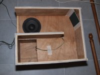
Background - the "reflectors" were sized to ensure that they would not reduce the cross-section d at any point below the constant cross-section used through the pipe. As I indicated, I used matt-board to make the reflectors. If you believe this is too thin to make a difference, I can repeat the test with something stiffer (perhaps sticking a few together to make a seriously stiff panel). I'll come back to this in a moment.
To make sure everything else remained constant, I taped the mic to the floor at the measuring position, the box was not moved while I changed its innards, and amplifier level and signal level (from HolmImpulse) were untouched throughout the test.
See images below. All raw response, measured via HolmImpulse.
The first image shows the FR with no reflectors.
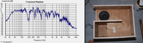
The second image shows the FR with one "reflector" added as indicated.
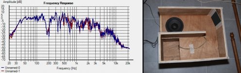
The third image shows the FR with two "reflectors" added as indicated.
They both show that the major differences are occuring way outside of the passband (>400 Hz).
And before anyone says "Brian, you plonker, those "cards" are too thin and are not going to make any difference at lower frequencies no matter where you put them in the pipe", I did find one or two locations where they DID make a significant difference to the response in the "notch" area. I can provide more details if anyone's interested.
Attachments
The 1/4W resonators are not for the FR peaks. The are to dampen the harmonic content from other frequencies that get boosted by the horn. Let's say the horn has a peak at 80Hz. You can add EQ to lower this peak, but that only effects that one frequency. Now you have a real driver playing a 20Hz tone loud enough to distort. The 2nd harmonic distortion is now being boosted to higher levels by the horns natural peak at 80Hz, and there is nothing you can normally do about it. Enter the 1/4W resonators.
TH's are 1/4WL resonators, closed end air columns. Most all bass horns are at the cutoff.
yes, I have done research on this -- more than you know. However anything I post you want to argue with, because you must know better than me.
I tire of this, however I will attempt at least one more time to clarify, because you are obviously intentionally missing what I am trying to communicate.
The 1/4 wave resonators... they work at the FUNDAMENTAL and ODD ORDER harmonics.... Closed ended resonators DO NOT DO ANYTHING AT THE 2nd ORDER HARMONIC... (like your example.) If you want to filter out the odd order harmonics of your horn... you by necessity MUST filter out some of the fundamental. If you design your resonators to hit a specific harmonic as it's fundamental...then what? what is an odd order harmonic of an odd order harmonic? (answer, nothing you care about.) you'd need a wind chime set of resonators to do any good. It makes MUCH more sense (and is 'obviously' what tom did) to tune the resonator to an IN BAND frequency, and then intentionally design a large response spike. The spike and the resonator will counteract each other, and what's left???? the ability for that resonator to filter odd order harmonics. By necessity, when you design a TH with 2 large peaks, there will be a large trough between them, that a series inductor will help with. THAT's the explanation of the dts-20 in my mind.
You obviously did not get my clarinet reference, so I'll try AGAIN... to get it communicated. A clarinet at the mouthpiece is not closed -- but yet it functions as a closed ended 1/4 wave resonator. (clarinet acoustics are well defined... use google) A high pressure wave enters at the reed, bounces off of the blunt end of the inside of the mouthpiece, and then propagates to the low pressure end of the clarinet.... AS A QUARTER WAVE RESONATOR. Well guess what I was thinking happens in a blunt end to blunt end section of a tapped horn where you start with a high pressure wave, that then goes to low pressure at the other end? I was guessing it was similar effect to a clarinet -- THAT'S why 1/4 wave resonances seem to pop up where you would only expect 1/2 wave resonances. A clarinet is open both ends, but doesn't act that way, and I was speculating that a TH segment could do the same.
I will typically only put reflectors on the 'high pressure side' of a TH segment, as this seems to be where I get the most effect. Again, it relates to the clarinet example. I know on my sax / clarinets, that the shape of the mouthpiece makes a HUGE difference in the tone. Even a few degrees makes a difference.
Sorry Brian for the bad timing of my joke (I should use smiles next time, huh). Even if the card works as a panel resonator it still would show some efficiency at the 170/200Hz dip wouldn’t it, so don’t worry. You have proven more then enough...
Anyway, conclusions so far (and correct me again when I'm wrong):
1.) To optimize TH (and this post is about Anders THAM in case anyone forgot) the use of “volume optimizers” in corners of a horn can have a positive effect. Their slope isn’t important since they don’t work as reflectors.
2.) The big dip around 170Hz of the THAM MKI is partly the result of the expansion in 90 degree corners.
3.) Like in room acoustics reflecting panels in a horn can only work if they have ½ wavelength surface to reflect anything above its own ½ wavelength frequency (but the reality is they never will fit in...)
4.) An “object” at ¼ wavelength from strategic points (mouth, driver) is nothing more then a path obstructer.
5.) Sections within a horn are nothing more then ½ wavelength open pipes although their influence is marginal if any.
6.) It remains to been seen, if possible, the Tham can work properly towards 250/300Hz (without electronic correction).
Last edited:
Please, include impedance measurements.
Perhaps the next round. First thing is to confirm if there are any significant changes in the passband. If so, then next step is an impedance check to see if the FR change is mirrored by a change in impedance.
That matt-board looks a little flimsy though (?), and the size should be about double (going to about the middle of that turn).
Yup, it's a bit flimsy, but the matt-board "cards" are also quite small too and supported on all four surfaces once the side's put back on, so they don't bend that easily
. If I have some time tomorrow, I'll stick a bunch together and repeat the tests to see if that makes any difference. Concerning the size, some rough calculations suggest that they cannot be more than 6.5" wide, otherwise they'll start to constrict the bend. I opted for 5.5" wide to be on the safe side.
That's why to me the information that screamerusa and jbell have provided - pertaining to the effect of shallow (12 to 15 degree) reflectors placed at the first bend(s) after the driver entry near the throat - is so valueable.
It's unfortunate that I could not check that effect in this round of tests. I thought the other side of this enclosure was also removeable, but turned out that it's nailed and glued in, so I don't have enough access to that part of the pipe to insert any reflectors
.
Last edited:
1.) To optimize TH (and this post is about Anders THAM in case anyone forgot) the use of “volume optimizers” in corners of a horn can have a positive effect. Their slope isn’t important since they don’t work as reflectors.
That needs to be empirically confirmed, but yes, any signficant constriction in the horn will alter its response in the passband.
2.) The big dip around 170Hz of the THAM MKI is partly the result of the expansion in 90 degree corners.
Nope - it's predicted by HornResp, which assumes a horn with no bends. It's a function of the alignment (the combination of driver and horn parameters)
3.) Like in room acoustics reflecting panels in a horn can only work if they have ½ wavelength surface to reflect anything above its own ½ wavelength frequency (but the reality is they never will fit in...)
Agreed.
4.) An “object” at ¼ wavelength from strategic points (mouth, driver) is nothing more then a path obstructer.
Agreed
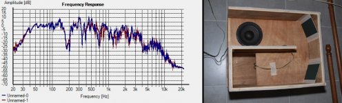
I did find one or two locations where they DID make a significant difference to the response in the "notch" area. I can provide more details if anyone's interested.
Here's one example of that effect. I basically randomly chose a place to put two additional matt-board cards to restrict the pipe at one point. The end result was that the "notch" got filled in a bit, with possibly a slight reduction in the response at frequencies at the lower end of the passband. Maybe this requires further investigation, e.g perhaps determining at which point in the horn the constriction would have the maximim impact on the depth of the notch, and the best height and width for the restriction.
Attachments
Yep, you're right, although Anders told us an improvement in this area after he fitted his corner “volume optimisers” it isn’t projected in HornResp anyways. So what is the proper translation for the conclusion about the 170Hz dip?
HornResp probably can't model what he did because it does not allow enough sections in the model to do so. However, the observations that Anders reported seem to be exactly what would happen if you take his HornResp model and start altering the expansion characteristics of the horn. The "W" shape will show up in the notch. I don't think it's necessarily an improvement, as you're replacing one notch with two
. What we'd like to do (if the intent is to extend the horn's passband) is to fill the notch in completely. If the results of my tapped-pipe tests are any indication (I will have to do more tests), it might be possible to do just that by inserting a properly-sized restriction in the path of the horn at the correct spot, and this "optimum spot" is likely not at one of the bends, but at a distance down the line that's determined by the center frequency of the notch.Hi Brian,
Thanks for the measurements. I feel that they do not simulate what is happening in the initial sections of the SS15 or the fury horn. The aspect ratio of the duct, and the direction of rotation is quite different. I agree, that going by anthing you can find in standard acoustics theory these small reflectors should not be doing anything in the operating frequency range of your tapped horn, they are just too small in comparison to the wavelength involved. As to other restrictions: I'm always surprised how small you can make the Ap1 (throat chamber port area) in Hornresp without markedly reducing the SPL response, I wonder if that holds true at high volumes, or if the losses grow to be too big?
Hi jbell,
Thanks for clarifying your views on the 1/4 wave resonators, I agree. It is also important to remember, that their Q can be tuned, e.g.: with light polyfiber stuffing.
I finally got the clarinet reference. That's a neat thought model.
Regards,
The 1/4 wave resonators... they work at the FUNDAMENTAL and ODD ORDER harmonics...
What you're leaving out in your analysis is how efficiently the 1/4 resonator works at the fundamental as compared to the odd order harmonics. Unfortunately I can't seem to find any experiments online that attempt to address this.
- Home
- Loudspeakers
- Subwoofers
- THAM15 - a compact 15" tapped horn