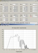
Now translate that back to your design. Your plots shows a very nice 36dB dip around 170Hz
Yes, and it also shows up in the HornResp SIMULATION. HornResp does not know and does not model how my horn was folded. The dip you're seeing is a product of the ALIGNMENT, not the box geometry. Your analysis of the horn's FR is incorrect, and therefore so are your conclusions.
djim, whats up with your interpretation? the simulation is clearly shown and its of the unfolded horn with a perfect expansion and no parallel sides (shown with dip). Brian's sim, measurements and graphs clearly support his conclusion.
Yup, I swear, when I read that interpretation, an old joke immediately came to mind:
The common fly has its ears on its wings. I know this because when there's a fly on the countertop and I clap my hands, it flies off. However, if I remove its wings first and then clap, it doesn't. It's therefore only logical that its ears are on its wings because it can't hear me clap when I remove them
") .
.BTW, have a look at my graph again. I indicated that the first standing wave will occur at around 350 Hz. Subsequent standing waves will occur at multiples of that frequency. See the dip in the measured response around 700Hz? What's that a multiple of?
.Yep , I noticed my mistake (and it was noticed to me already in an e-mail) but couldn't edit no longer. Although the first half is still standing...
Djim, at this point I can only suggest that you get your hands on a copy of of Everest's Master Handbook of Acoustics and have a good read, particularly about what it has to say about room modes and standing waves. Your suggestion that standing waves start at 1/4L is simply not supported.
Jbell, the thing that would convince most die hard, evidence based people are the the measurements that you have yet to provide.
I invite you to show unsmoothed spl graphs, and impedance over the range in question.
I for one I'm not questioning JBell's observations. It's the conclusions about the cause of the changes he's observed is what I'm questioning. I don't think "standing waves" have anything to do with it at all.
Brian Steele has been correct the last few pages.
Standing waves are 1/2WL based.
In room issues at 1/4WL distances are time/phase base, and are also 1/2WL cancellations. 1/4WL from the speaker to the wall. 1/4WL back from wall to the speaker. There is now a 1/2WL time/path difference with a 180deg phase difference = null.
Standing waves are 1/2WL based.
In room issues at 1/4WL distances are time/phase base, and are also 1/2WL cancellations. 1/4WL from the speaker to the wall. 1/4WL back from wall to the speaker. There is now a 1/2WL time/path difference with a 180deg phase difference = null.
So I was wrong and Brian was correct, first standing wave between two walls is ½ wave and not ¼ wave as I assumed!
But if my ¼ waveform theory isn't right for the Tham (or Jbells example) it was nothing more then a lucky shot and has nothing to do with standing waves and my reflectors shouldn't work, correct?
Then I'm wondering why my reflectors and Jbells do work (or do we see ghosts?) and what is the correct theory to deal with these issues?
Hello all
WOW ! Just my luck being cut off from the www just as my thread here explodes with creativity, I should be back online by the end of next week (writing from my office at the moment).
It stikes me that i might have hit the hornetsnest with a solid 2x4 here, and I'm very happy to see all the brilliant minds at work trying to give me a helping hand.
I also see that i no longer have any control of the THAM15's future, wich is perfectly allright and actually the way I would like to see it to evolve.
IF, that is, you all feel that the design in it's most basic form is smoething worth your while and efforts to improve, then I'm happy to step back and let it run it course.
I fell it is now out of my hands, both knowledge-wise, and also with regards to the spread that this design has now gained, and I'm more then happy to let it go knowing that some of you out there are still finding it usefull.
I hope it will live on, and I'm happy yo have been able to contribute and give something back to all of you out there now trying to improve upon it, my resources are limmited in comaprison to what i feel i should do, build, test, provide results and so on, my mailbox is recieving alot of questions and I'm not allways albe to answer.
Just seeing your comitment and dedication to the designflaws warms my engineering hart, simply saying thank you feels a bit lame as it is much more then that.
It is clear to me now that my efforts in trying to improve my basic design may be (remains to be seen) futile, it flaws may be in the basic design itself, it does suffer from defects, the 180-dip, the folding at the appature end and so on, my intention was to design a small, simple to build TH wich provides well for it´s size, and i still hope that the THAM15 is up to the international standards of DIY that i now find myself in.
I will not give up though, no way, I'm having a great time here much thanks to all of you, and I'm learning alot.
I really hope you (and my self) find some way to even the response out, my attempts sofar has yielded only small improvements of an almost academic nature, if these flaws can be resolved, if you find a way to improve it, please post your findings and i will revise the plans and give the credit back to where it blongs, back to all of you.
The design is now yours, in true open source style, do not ask for premission to alter it, just do it, in my mind it has allways been that way since i first introduced it to you, please make it a good one, i will still try to contribute no matter how simple my sugestions might be in comparrison.
In the light of all your knowledge it would be down right wrong of me to think i got it 100% right from the start, even if i do feel i got of to a good start and that the THAM15 is still in the field of designs worth checking out when considering a build, and i hope you agree.
Now - go crazy !
For what it's worth:
Hi guys,
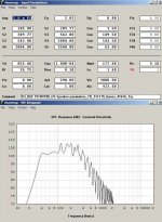
Maybe the problem is not so much in the details as it is in the design limitations. Looks to me, that the THAM 15 is designed to minimize volume and to maximize ease of construction, which is why it looks like the TD TH-MINI; as compared to the TD TH-115, which seems to be optimized towards extracting the best possible SPL response from the B&C 15TBX100. From my simulations of tapped horns with this driver I like a minimum of something around 200 liter_net in Hornresp.
As to the reflectors: it was Tom Danley that told the story about comparing a shop prototype of the LAB horn to an elaborately build version with rounded internal corners. He found that the shop prototype outperformed the other build, and that the reduction in internal volume may well be the culprit.
Just for fun I'll attach two simulations, these have not been folded, and converted into drawings (in other words, just food for thought):
Regards,
Hi guys,
Maybe the problem is not so much in the details as it is in the design limitations. Looks to me, that the THAM 15 is designed to minimize volume and to maximize ease of construction, which is why it looks like the TD TH-MINI; as compared to the TD TH-115, which seems to be optimized towards extracting the best possible SPL response from the B&C 15TBX100. From my simulations of tapped horns with this driver I like a minimum of something around 200 liter_net in Hornresp.
As to the reflectors: it was Tom Danley that told the story about comparing a shop prototype of the LAB horn to an elaborately build version with rounded internal corners. He found that the shop prototype outperformed the other build, and that the reduction in internal volume may well be the culprit.
Just for fun I'll attach two simulations, these have not been folded, and converted into drawings (in other words, just food for thought):
Regards,
Attachments
Adding material will always alter the FR. What BS has been trying to do is help you to determine what it was that caused the change.But if my ¼ waveform theory isn't right for the Tham (or Jbells example) it was nothing more then a lucky shot and has nothing to do with standing waves and my reflectors shouldn't work, correct?
Then I'm wondering why my reflectors and Jbells do work (or do we see ghosts?) and what is the correct theory to deal with these issues?
First I would check things out in AkAbak to see if it was a simple volume change in the right area that caused the majority of change. If that doesn't immediately pan out the next route is good measurements, including system Impedance. These should be done in the near field, as you only want the cabinets response. Once you add distance and power you start getting into the loud signal behavior which can be a bit different, especially in a small folded horn.
Check out BS's site for why the Impedance measurement can be more helpful here than FR.
Check out BS's site for why the Impedance measurement can be more helpful here than FR.
Link: The Subwoofer DIY Page v1.1 - Projects : Using Impedance Graphs
wow, step away for a bit, and I missed a bunch of discussion on this.
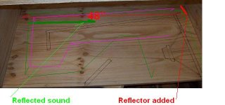
What's missing in my mind in the last couple pages of discussion is the fact that everyone is assuming we are talking about a SINGLE wave bouncing between 2 surfaces. we are not. There are at minimum 2 waves, and actually more than that in play. When a wave hits a blunt surface, less than 100% goes around the corner. What gets reflected instead of transmitted is now of concern. (in addition to the 2 waves, one from the front and one from the rear of the driver.) If you have 2 waves 180 out of phase, you get a cancellation. This is what I heard in my 2x2x4 cabinet without the bottom reflector. It was a muffled out of phase sound that was way down on spl. By adding ONE reflector, I was able to eliminate that. The one reflector was at the bottom of a 48" long path, which happens to relate very well to the 70hz issue that this cabinet had. Without the addition of this one reflector, this cabinet was destined for the burn barrel.
So... you can create nulls that hornresp doesn't predict, and you can eliminate nulls that hornresp does predict based on your folding and reflectors in a cabinet in my experience.
call it standing waves, call it phase cancellations, whatever you want -- it does happen.
Attachments
What's missing in my mind in the last couple pages of discussion is the fact that everyone is assuming we are talking about a SINGLE wave bouncing between 2 surfaces. we are not. There are at minimum 2 waves, and actually more than that in play. When a wave hits a blunt surface, less than 100% goes around the corner. What gets reflected instead of transmitted is now of concern. (in addition to the 2 waves, one from the front and one from the rear of the driver.) If you have 2 waves 180 out of phase, you get a cancellation. This is what I heard in my 2x2x4 cabinet without the bottom reflector. It was a muffled out of phase sound that was way down on spl. By adding ONE reflector, I was able to eliminate that. The one reflector was at the bottom of a 48" long path, which happens to relate very well to the 70hz issue that this cabinet had. Without the addition of this one reflector, this cabinet was destined for the burn barrel.
The only problem with that theory, and it's a BIG problem, is IMO that reflector is simply too small to have any significant impact on a 70 Hz wave.
So... you can create nulls that hornresp doesn't predict, and you can eliminate nulls that hornresp does predict based on your folding and reflectors in a cabinet in my experience.
My own tests have shown that those changes only occur ABOVE the frequencies predicted by 1/2L, where L is the distance between the two walls being considered. Seems to the the point at which horn geometry starts to make a difference. The frequency response chart I previously posted, which examines a worst case scenario, demonstrates this.
I'm not arguing that the change in response does not happen, JBell - after all, it's your observations. However, attributing it to "standing waves" or "phase cancellations caused by reflections" that can somehow be modified by small (relative to the wavelength being discussed) reflectors is IMO incorrect. The wavelengths of the frequencies being discussed are simply too long.
Based on my own observations in the admittedly only two proof-of-concept designs I've built, the biggest potential robber of low bass performance seems to be improperly sealed joints, and the biggest potential robber of upper bass performance seems to be panel flex. And for the boxes sizes under consideration, that can fall right into the 70 Hz area you're talking about. For my last POC, which is a smaller box, I've measured and observed "close-miked" response differences in the 90~200 Hz region by simply mounting the box on a mat that damps the vibrating panel, for example.
I think getting rid of that notch in the THAM15 (if we actually WANT to do that) is going to require a different approach however, as increased bracing to eliminate panel flex is likely going to move the measured results closer to the HornResp's predictions about the size of the notch and where it occurs.
I'd like to suggest that perhaps some sort of closed pipe or hemholtz resonator might be a predictable and effective way of dealing with the notch in the THAM15 design. This resonator could take the form of an extra chamber to the back or bottom of the box that's vented into the horn at 1/2L(or maybe at the beginning of the horn - I'm not sure). As to how big that vent and chamber should be, I've got no clue at this point, as not only is the resonant frequency important, but also the 'Q' of the resonance. It's also possible that the space taken up by the resonator could be used instead for a different horn geometry that more effectively deals with the notch.
The only problem with that theory, and it's a BIG problem, is IMO that reflector is simply too small to have any significant impact on a 70 Hz wave....
I'm not arguing that the change in response does not happen, JBell - after all, it's your observations. However, attributing it to "standing waves" or "phase cancellations caused by reflections" that can somehow be modified by small (relative to the wavelength being discussed) reflectors is IMO incorrect. The wavelengths of the frequencies being discussed are simply too long..
Simple way to prove this, you see the design of the box, it's 2x2x4. go get you some cheap cdx, or even flake board subfloor that's about $15 a sheet. Build it and test, roast hot dogs when done.
There is no substitute for doing.
Simple way to prove this, you see the design of the box, it's 2x2x4. go get you some cheap cdx, or even flake board subfloor that's about $15 a sheet. Build it and test, roast hot dogs when done.
There is no substitute for doing.
That may prove the RESULT, but not the CAUSE.
Brian, would you be so kind to share a drawing/picture of your tapped pipe from your plot (post # 56)?
See link: The Subwoofer DIY Page v1.1 - Projects : A "Proof of Concept" tapped pipe** - introduction.
As I indicated, it's a very simple design, but seems to work quite well, particularly when partly stuffed. The "3D" design results in the internal panels acting as braces for all sides. It's also easy to convert it into a horn with one expansion rate, by angling the internal divider that holds the driver.
That may prove the RESULT, but not the CAUSE.
No matter the geek and the engineer in me -- I will tell you with a straight face, and in all sincerity -- I don't care about the cause, as long as I know what results in what. Yes I'd like to know, no I don't have to know.
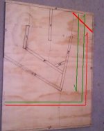
Here's an example. I know that If I put in a reflector in red where shown, it'll cut my overall response, and especially my 100hz area response. I have a theory that some of the wave traveling back down the horn gets reflected back, emphasizing the 100hz, and also reducing the 'back pressure' in the horn allowing the lower frequencies more total output.
It's a theory -- is it right? I'm betting not. Do I care? no. I know it happens, so all of my TH's lately, I make sure there is a place where there is an intentional lack of a reflector in this location just for this reason.
Another case... a solid rear brace along the long back of that design cuts 40hz by 2db. why? more bracing should be better, and louder -- less loss through panel flex. Hollow bracing or even my 2 braces as designed in the ss15 reduce, but don't eliminate that rear panel flex. But it's louder than a solid brace.
again, why? don't know, I don't have time to figure the why out... it's taken me too much time as it is just to figure the what part out.
right now I have a design that I'm happy with, In single cabinets it does 98.5@40hz, 100@42hz, and smoothly runs up to 105@60, and is flat from there up through 200hz. In pairs or quads it's downright impressive and much flatter below 60hz. For pa, in my book, that's pretty darn good. I've posted smaart readings, outdoor showing exactly what this cabinet can do, oliver has posted cad drawings so anyone can replicate if they want.
That particular cabinet does a couple things that I don't have answers to... but again... I am just happy with the results.
Attachments
- Home
- Loudspeakers
- Subwoofers
- THAM15 - a compact 15" tapped horn