No disrespect to Tom but could that be wrong? AndyTom has commented that sharp bends should be closer to the throat, not the mouth
Brain, its all about a quater of wavelength not full wavelengths...
Ok...
1/4 wavelength of 70 Hz is about 4 feet. How is a 5" reflector going to "reflect" this in any appreciable way? That's a bit like trying to stop and change the direction of an ocean wave with a spoon (ok, that may be a bit of an exaggeration, but still)...
Based by your diagram, *maybe* replacing part of one parallel surface with a surface with a shallow slope might change the 'Q' of the resonance between the two walls a bit. This might explain why a shallow slope works better than the steeper 45 degree reflector. But then again we're talking about a 5" difference, max.. The mathematicians here can work out how much the Q will change with that difference (it's Friday night and my mind is more on beer instead, LOL), but I suspect that it's not going to be much. However, it should be possible to get better results by just lining one side (e.g. the end closest to the driver) with enough fill to cut that resonance significantly.
Further down the horn the reflectors will get larger, and therefore more effective at lower frequencies. But still, none of them approach 4 feet in width...
Hi there Anders: With regard to adding 45 degree (or similar size) deflectors, MK II & III versions may be signifiquently reducing the total cabinet volume, possibly as much as 15-20L ( estimated: 4@ [13x13x50] + 1@ [15x15x50]/2=[5625 +16900]=20+L. This much reduction may effect the response of the TH, just as lowering the box volume for other types of enclosures. ...regards, Michael
Brian:
I am obviously not going to change your mind, or convince you of anything. I will not try. I will respectfully disagree with you, and state that a single reflector can in fact make a huge difference in a TH, that I actually measured.
I have built and rebuilt dozens of TH's. Each time I measured. Each time I learned. There have been many bonfires of the carcasses of the under performing.
It's kinda like the old saying about two farmers arguing about how many teeth a horse has. The argument stops when one of them opens the horses mouth and looks.
Brian:
I am obviously not going to change your mind, or convince you of anything. I will not try. I will respectfully disagree with you, and state that a single reflector can in fact make a huge difference in a TH, that I actually measured.
I'm not questioning your observations. Just trying to determine the actual cause. Once the actual cause is known, the next step is determining how best to optimize it. Could lead to less bonfires
")
Last edited:
Well Brain, the problem(s) with acoustics is often more complex then our first thoughts, especially on Friday nights! BTW in an open-field environment you would be right. With a spoon you can’t stop an ocean wave, but sure a spoon (with enough backup) can bend a beer ‘jet stream’ that is leaving a barrel under pressure. This is a matter of controlling environmental circumstances. A horn is all about controlling the environment for the sound waves.
Now back to your question; sound waves with bigger wavelengths then the surface they reflect from, will simply bend. They can’t leave the box nor causes the corner enough friction to change the energy of the sound waves into heat. So for the sound wave there is only one solution and that is bending and following the path we carefully set out for them.
Standing waves however are the result from sound waves bouncing (reflecting is a better word actually) between two parallel surfaces. The more bends we have in a horn the more parallel walls are introduced and the more ‘spiky’ the outcome will be.
Every bend in horn design means a loss in energy by the introduction of unwanted physical side effects. One of problems is a different expansion factor within the bend. The other factor is that the waves runs into a straight wall and can possibly change into a standing wave. In that case the energy will partly bounce forwards and backwards between the walls until its energy is gone (actually changed in another form of energy).. This we will hear (and see in our measurements) as a dip.
With reflectors you can strive to a more optimum wave bend with less differences in the expansion path and more importantly to prevent standing waves. If you make the reflector to big it will influence the horn path negative by obstructing the sound wave instead of bending it. If you make it to small it wont have the effect (or minimal) what you are after.
Hopefully this makes sence at half past seven (my time) cause it aint no longer to me...
Standing waves however are the result from sound waves bouncing (reflecting is a better word actually) between two parallel surfaces. The more bends we have in a horn the more parallel walls are introduced and the more ‘spiky’ the outcome will be.
I agree with all you're saying there. However, the standing wave problem occurs between parallel walls when the wavelength of the sound being produced is twice the distance between the walls. If you look at the dimension of the box being discussed here, that's puts the standing waves over 280 Hz (guesstimate). Yet JBell says he's observed significant (4dB) improvement at less than quarter of that frequency by using in a shallow reflector.
Nope Brian, standing waves start to occur between walls at a quarter of the wave length (and half wavelength and full wavelength).
If you look at Sanders Tham, you see 3 places where standing waves can develop (and they all have similar length). My point in the picture of post # 37 was that Jbells suggestion for reflectors will not deal completely with the standing waves because of two reasons:
1.) There are still enough parallel surfaces where standing waves will develop (I marked that with the green area). Jbells example of his significant improvement of 4dB was to solve his problem at 70Hz. This means he had two parallel walls around 122cm (48inch) causing a standing wave.
2.) The second reason needs more explanation. How a relative small and shallow reflector can give such results is a matter of careful placement and understanding of standing waves. In literature (published in AES papers for example) you will find experiments that show that walls start to suppress standing waves as soon they have a > 10 degree difference. However this is frequency related. The higher the frequency the bigger the angle you need. If you want to suppress standing waves over the whole spectrum you need an angle of about 30 to 40 degrees between the two walls. That’s why most walls in recording studio’s have each a traditional angle of about 15 to 20 degrees.
Now, Jbells 4 dB example was at 70Hz and Anders Tham problem is around 175Hz. It means that a similar angled reflector of 12 degrees for the Tham is not going to be as effective. Therefore I suggested more steep angles. The problem with steep angled reflectors is they start to narrow the horn path. Instead of reflecting they start to obstruct the sound waves. That’s why I think you cannot get away with just 2 reflectors as Jbell suggested. In my opinion the Tham would benefit from multiple reflectors that ‘see’ each other. But the use of multiple reflectors will give unwanted side effects and Jbell was trying to warn us for that...
Last edited:
Nope Brian, standing waves start to occur between walls at a quarter of the wave length (and half wavelength and full wavelength).
I think this is incorrect. 1/4L is where the distance in question can't support a wave of length L and frequencies at or below this point tend to produce changes in pressure across the area, rather than waves. This is discussed in Dickason's Loudspeaker Cookbook. Also, if you have it, have a look at Everest's discussion of "two-wall resonance" in his Master Handbook of Acoustics. The first mode starts at 1/2L, not 1/4L. Two walls separated by distance L will have the first standing wave mode occuring at the frequency given by 1,130/2L, where L is the distance in feet.
Finally, I found a java script on the Internet that demonstrates the development of standing waves - see Generate wave on rope. You will note that the first standing wave starts at 25 Hz, and the moving illustration shows half a waveform. Lower frequencies don't produce any standing waves on the string.
Nope Brian, standing waves start to occur between walls at a quarter of the wave length (and half wavelength and full wavelength).
If you look at Sanders Tham, you see 3 places where standing waves can develop (and they all have similar length). My point in the picture of post # 37 was that Jbells suggestion for reflectors will not deal completely with the standing waves because of two reasons:
1.) There are still enough parallel surfaces where standing waves will develop (I marked that with the green area). Jbells example of his significant improvement of 4dB was to solve his problem at 70Hz. This means he had two parallel walls around 122cm (48inch) causing a standing wave.
2.) The second reason needs more explanation. How a relative small and shallow reflector can give such results is a matter of careful placement and understanding of standing waves. In literature (published in AES papers for example) you will find experiments that show that walls start to suppress standing waves as soon they have a > 10 degree difference. However this is frequency related. The higher the frequency the bigger the angle you need. If you want to suppress standing waves over the whole spectrum you need an angle of about 30 to 40 degrees between the two walls. That’s why most walls in recording studio’s have each a traditional angle of about 15 to 20 degrees.
Now, Jbells 4 dB example was at 70Hz and Anders Tham problem is around 175Hz. It means that a similar angled reflector of 12 degrees for the Tham is not going to be as effective. Therefore I suggested more steep angles. The problem with steep angled reflectors is they start to narrow the horn path. Instead of reflecting they start to obstruct the sound waves. That’s why I think you cannot get away with just 2 reflectors as Jbell suggested. In my opinion the Tham would benefit from multiple reflectors that ‘see’ each other. But the use of multiple reflectors will give unwanted side effects and Jbell was trying to warn us for that...
You are so right on the money with this analysis.....
Attachments
Last edited:
You are so right on the money with this analysis.....
As the fundamental premise that standing waves between two surfaces starts at 1/4L is likely incorrect (Everest, an authority (if not "THE" authority) on room acoustics is just one reference I've found on this), the rest of the analysis that's based on this premise falls apart IMO.
One more thing...
The THAM "problem" is actually predicted by HornResp sims and therefore has nothing to do with the physical layout of the horn in the box (HornResp assumes one continuous horn with no bends). The dip has everything to do with the path length and expansion rate(s) chosen for the TH. By using two expansion rates, it may be possible to reduce or eliminate the nulls and extend the passband, possibly at the expense of LF cutoff. JBell's SS15 is acutally a good example of this. IMO, if the predicted dips in the response are outside of the horn's target passband, then IMO they are not worth worrying about.
Now, Jbells 4 dB example was at 70Hz and Anders Tham problem is around 175Hz.
The THAM "problem" is actually predicted by HornResp sims and therefore has nothing to do with the physical layout of the horn in the box (HornResp assumes one continuous horn with no bends). The dip has everything to do with the path length and expansion rate(s) chosen for the TH. By using two expansion rates, it may be possible to reduce or eliminate the nulls and extend the passband, possibly at the expense of LF cutoff. JBell's SS15 is acutally a good example of this. IMO, if the predicted dips in the response are outside of the horn's target passband, then IMO they are not worth worrying about.
As the fundamental premise that standing waves between two surfaces starts at 1/4L is likely incorrect (Everest, an authority (if not "THE" authority) on room acoustics is just one reference I've found on this), the rest of the analysis that's based on this premise falls apart IMO.
Brian:
As I said a few posts ago... I'm not going to convince you of anything.
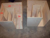
When you build the cabinets, test the cabinets, change the reflectors and then retest -- then we can have a discussion. Building one or two cabinets and only adding bracing as your effort of 'improving' the cabinets... well that doesn't address the standing wave discussion we are having. If you've never built a cube or some cabinet with dimensions that are all multiples of each other -- you've never seen an extreme example of standing waves, so therefore you dismiss it as 'not possible.'
Part of the reason I abandoned the cube was for this reason, I was always messing with the reflectors...
Attachments
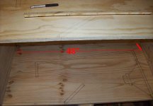
One more study on standing waves and where they actually occur...
My POC#1 is basically a tapped pipe, split into four equal sections of about 19.5" each, then jointed together to form a box. Now, this should produce the WORST possible result with respect to standing waves, as three of the components of this box have walls that are the same distance from each other (19.5").
According to Everest, the first standing wave should occur at (1130*12/(2*19.5), which works out to approximately 350 Hz.
Now, here's an actual measurement of that alignment:
The green line is the predicted response from HornResp.
The blue line is the measured response. It shows several things, amongst this being (1) the driver was not properly sealed to the box, hence the dip and peak at the lower end of the passband, (2) the effect of a 100 Hz 12dB/octave LP filter, (no surprise there - I was driving the sub using the subwoofer channel from my receiver), but I want to bring your attention to is (3), the point at which the predicted peaks and nulls start to depart from HornResp's predictions. From the graph, it's clear that this is starting to happen above 300 Hz and actually closer to 400 Hz - a very good correlation to the 350Hz fundamental predicted by the above equation, above which the response will be affected by the box geometry.
If you've never built a cube or some cabinet with dimensions that are all multiples of each other
Actually I've done just that, measured it, and referred to it in my previous post
.Another try...
You are right in room acoustics, first standing wave is at ½ wavelength. This results in your room as upwards spike, the ringing effect, the boost which some people seem to adore in their low end...
But we are talking dips here! And where in your room you have these dips? Perhaps at a quarter wavelength? I’m sure you can find somewhere in your books a subject about losing low frequencies at the mixing spot in home studios. Doesn’t matter if you use Dynaudio’s, Genelecs, Adams or cheap KRK's (please, no offence KRK users). They all seem to suffer from the same bad room acoustics. The reason is simple; most home studios have their monitors up the front wall and sitting behind their mixing desk/DAW station at ¼ in the room. (what was it called in English? Nuts and anti nuts?!)
Now translate that back to your design. Your plots shows a very nice 36dB dip around 170Hz
342m/s : 170Hz = 2,01m : 4 (quarter wavelength) = 50cm = 19,8inch
I’m sorry I’m 3/10 of an inch off!!!….shame on me.
You are right in room acoustics, first standing wave is at ½ wavelength. This results in your room as upwards spike, the ringing effect, the boost which some people seem to adore in their low end...
But we are talking dips here! And where in your room you have these dips? Perhaps at a quarter wavelength? I’m sure you can find somewhere in your books a subject about losing low frequencies at the mixing spot in home studios. Doesn’t matter if you use Dynaudio’s, Genelecs, Adams or cheap KRK's (please, no offence KRK users). They all seem to suffer from the same bad room acoustics. The reason is simple; most home studios have their monitors up the front wall and sitting behind their mixing desk/DAW station at ¼ in the room. (what was it called in English? Nuts and anti nuts?!)
Now translate that back to your design. Your plots shows a very nice 36dB dip around 170Hz
342m/s : 170Hz = 2,01m : 4 (quarter wavelength) = 50cm = 19,8inch
Quote from Brian: Now, this should produce the WORST possible result with respect to standing waves, as three of the components of this box have walls that are the same distance from each other (19.5").
I’m sorry I’m 3/10 of an inch off!!!….shame on me.
Last edited:
Brian:
As I said a few posts ago... I'm not going to convince you of anything.
Jbell, the thing that would convince most die hard, evidence based people are the the measurements that you have yet to provide.
I invite you to show unsmoothed spl graphs, and impedance over the range in question.
- Home
- Loudspeakers
- Subwoofers
- THAM15 - a compact 15" tapped horn