Cubo 15 extended seems to be the same size as the standard cubo 15 which is 238,3 dm3, THAM15 is 187dm3 making it roughly 22% smaller.
Regarding the out of (or above) passband response of these designs, this has been a source of much discussion, primarily regarding integration (i have yet to se this as a real world issue) buyt I belive that a flat responce (spl) above the passband makes sence, but it would really hard to make it work well in the time domain, which would not resolve integration part of the argument.
Regarding the out of (or above) passband response of these designs, this has been a source of much discussion, primarily regarding integration (i have yet to se this as a real world issue) buyt I belive that a flat responce (spl) above the passband makes sence, but it would really hard to make it work well in the time domain, which would not resolve integration part of the argument.
I've been working on and off on a series-tuned 6th order BP layout that demonstrates much better out of band noise suppression while still keeping a useful wide passband
The ROAR15 is a 8th order BP layout with much better out of band noise suppression and a large wide usable passband. It works great!

Regarding the out of (or above) passband response of these designs, this has been a source of much discussion, primarily regarding integration (i have yet to se this as a real world issue) buyt I belive that a flat responce (spl) above the passband makes sence, but it would really hard to make it work well in the time domain, which would not resolve integration part of the argument.
It looks like you're looking at the issue just from the perspective of the system reproducing just the input signal. The out of band response also impacts the amount of distortion that the system produces when trying to reproduce that input signal, e.g. a response curve "spike" at 150 Hz is going amplify any distortion produced at 50 Hz.
A bandpass system then that exhibits a lot of out of band "noise" near or above the passband response is therefore missing one of the main theoretical advantages of a bandpass system - significant distortion reduction.
Whether or not that distortion is actually audible is subjective, particularly when the bandpass system used as part of a full range system, but based on my past experiments with bandpass alignments, a bandpass system with better out of band noise suppression always seems to sound a bit "cleaner". I will admit though that may involve a bit of "confirmation bias" on my part
.The ROAR15 is a 8th order BP layout with much better out of band noise suppression and a large wide usable passband. It works great!
FWIW, a large wide passband can also impact the system's ability to reduce distortion, but I guess that also depends on what driver excursion within the passband looks like too. For example, if driver excursion peaks around 50 Hz, I wouldn't want the system having any significant peaks in the raw response around 150 Hz. But again, the audibility of the distortion is quite subjective.
I've been working on and off on a series-tuned 6th order BP layout that demonstrates much better out of band noise suppression while still keeping a useful wide passband - hopefully I can get to building it before Christmas, just to see how it compares to my previous TH build....
Can't wait to see the build and results!
I thought the ROAR series are 6th order?
The lines are a bit blurred, but usually a tapped pipe/tapped horn is seen as 6th order quarter wave BP, and if you add a front resonator to a 6th order you get an 8th order.

Note that the shape of the resonator peak is somewhat less sharp, my suspision is that the intentionally generous volume of air in the resonator, or air load (mass) contributes to this shape, it might also stem from it being a secondary coupled load post summation, making it differentiate from the standard tapped horn impedance peak signature.
Either way, if going by the impedance peaks alone then yes, this is not a pure 6'th order system, schematicaly though one might reach other conclusions, it shows the resonator function as an addition to standard th approach, and it's impact is far from a narrow local one as it boosts the entire passband.
Either way, if going by the impedance peaks alone then yes, this is not a pure 6'th order system, schematicaly though one might reach other conclusions, it shows the resonator function as an addition to standard th approach, and it's impact is far from a narrow local one as it boosts the entire passband.
I'm guessing that the The little impedance peak between 100 Hz and 200 Hz is above the usable passband? I've so, I'd call that 6th order.
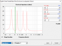
I've attached the sim'd impedance response for an 8th order system with a bandwidth from 40 Hz to just above 200 Hz. The 4 peaks are very prominent.
Attachments
The lines are a bit blurred, but usually a tapped pipe/tapped horn is seen as 6th order quarter wave BP, and if you add a front resonator to a 6th order you get an 8th order.
Nothing in the link below says 8th order enclodure to me. BeautifuI build and great blog though! I see a split path 2 stepped TH. The enclosure is modeled as a 4 segment TH. I think you could call it a regular series tuned BP6 due to the straight flare segments.
Martinsson's Blog - ROAR15
I'm guessing that the The little impedance peak between 100 Hz and 200 Hz is above the usable passband? I've so, I'd call that 6th order.
No. It is at 147 Hz and within the passband, and it is very much part of shaping it. It is clearly an 8th order per your "impedance-peak x 2" definition. The large front resonator cross section might have a lower Q amd a wider bandwidth and thereby a lower impedance peak then a comparable Helmholtz resonator.

The 4 peaks are very prominent
Your 210 Hz "prominent" peak peaks at 24 Ohm.
The 147 Hz forth peak of the ROAR15 peaks at 22 Ohm.
I hope those measly 2 Ohms does not disqualify the ROAR from the glorious world of 8th order bandpass alignments...


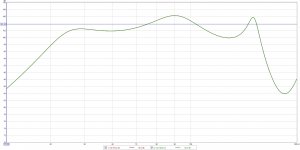
ROAR15 compared with the tapped pipe section without the front resonator.
As is easily seen in the impedance graph, the front resonator adds another impedance peak (the third one). The large front resonator has a quite low Q and very wide bandwidth (as seen in the spl comparison) and hence the impedance peak has a quite low Q.
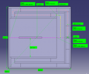
I take it that the 4th segment of 71.60cm creates the 8th order?
Yes. If the step up in cross section area is large enough and the section is long enough, then it acts as a separate resonator creating an 8th order.
T18
I like it! Can you give me some dims on an EV T18 scaled-down for a 12 inch Dayton pa310 driver!!!!!!!!!????????
Hello Johan
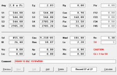
If i do the math on the dims only i arraive at your 187dm3 on the external dimensions, so far so good, and the S4 value tells me that the internal width is 464mm also a check, and the lengths L12,L23 & L34 are all correct in the sim.
My only naggin doubt is that the expansion may not be corretly simulated as the front chamber takes a step up in volume that is not shown in the system volume calculations.
Since this is a linear expansion (apart from the last step mentioned above) there maight be a deviation in there somewhere, the material part of the volume should be about 50dm3 (approx 12x24x0.18dm).
The differance between the volumes 187-173 = 14dm3 (given that the 173dm3 sim figure is correct) does not account for the material only, there is still a diff of approx 50-14 = 36dm3 left somwhere.
Now 36dm3 is not to be taken lightly, this is a significant amount of volume, a part of which can depend on the linear simulation of a non linear expansion, and the bends has been approximated, this maty also contribute, the sum of all this may give us the difference you describe.
Where and how these deviations are and lokk like, aswell as how great a apart they play remains to be figured out.
I will not change the design to fit the simulation, the simulations however may need another go to figure out exactly how this design simulates in detail, but the real world result is still, and has allways been, a very good one, the comments i have recieved sofar from users has been very positive.
Thanks for bringing this to my attention, I will as soon as possible try to iron this out, meanwhile me advice to all that are thinking about building this box is still "go for it", it works wery well, despite the suspected simulation errors.
If anyone out there wants to lend a helping hand in figuring this out and perhaps speed thing up please do so and let us know of your findings, i would be very grateful for any help i can get.
Best regards // Anders Martinsson
I like it! Can you give me some dims on an EV T18 scaled-down for a 12 inch Dayton pa310 driver!!!!!!!!!????????
How come you don't have 4 parabolic segments in the model?
Because there is no difference with straight non expanding sections.
Attachments
- Home
- Loudspeakers
- Subwoofers
- THAM15 - a compact 15" tapped horn