Are you writing about thermal compression (voice coil heating raising impedance) , or something else?
I'm writing about something else - theoretical output loss due to a restriction placed within the horn's path.
What is the power rating of the amp and speaker?
The Dayton PA310 is rated at 450W RMS. The amplifier is a Pioneer class-D model that's rated at being able to deliver 500W into 2 Ohms. Into the Dayton's 8 ohm nominal impedance, it should be able to deliver about 125W (or more ) RMS.
Most music has between 1/3 to 1/20th the average power of sine waves, 1/3 power would be approaching worst case dubstep or heavy clipping or compression.
Normal pink noise has 12 dB crest factor, so an unclipped 1000 watt amp is delivering less than 100 watts average.
It would take a very powerful alternator and lots of battery to deliver appreciable sine wave power for more than a short burst.
Not applicable to my testing. My first test involved a swept sine wave that varied from 30 Hz to 400 Hz (generated via HolmImpulse), played at 0dB, -6dB and -12dB below the amplifier's peak output capability into the speaker. The flatting of the response at the upper bass level suggested that my mike or input was being overloaded, so I redid the test, this time using a continuous tone at 40 Hz generated by TrueRTA that was started at 0dB and then stepped downwards one dB at a time, with TrueRTA's reading for input SPL rms taken at each step. Output vs. Input was then graphed - any sign of compression would have shown up as a curve in the graph, but the graph was basically a straight line.
Why the 40 Hz test frequency? Well, that's at just above the last impedance minimum in the horn's impedance response. The driver's cone barely moved during the test. This particular driver in this alignment is going to hit its Xmax limits within the passband @around 80W of input, so testing at a higher frequency would have run the risk of the driver's non-linearity excessively contributing to the results of the compression measurements.
Although Brian’s "dogfood" method seems to work it also seems to have a negative side effect; lowering gain/efficiency at LF. When you narrowing the horn’s path bigger then 1/6 of its dimension it clearly looses its efficiency. I’m not sure about the explanation but I think that narrowing, forces the same amount of air molecules to pass trough the small 'port'. This results in a heavier air mass which results in loss in energy.
Instead I’m wondering about expanding the hornpath at problem areas. The whole horn system is based on this principle. Expanding means lowering the airmass trough the path. This results in gain.
Now, when we expand on those corresponding places (1/2 wavelenght) where dips occur (as part of the design) maybe there is a change we can influencing the dip in a positive way without changing the efficiency at LF (the longer wavelengths will not ‘see’ the relative small expansion since it doesn’t correspondent to their frequency).
For the THAM I think there is this extra space/volume for dip-correction. If it generates enough extra volume is another question but maybe somebody with Akabak knowledge could help us here.
In my new suggestion for dip-correction you can see I get the extra volume from the corner correction at the other side. This will be around 1meter in the pathway. Probably this new suggestion works even better if the other two corners in the same segment have corner bracings (corner corrections).
1meter 1/2 wavelength has a corresponding frequency of 172Hz, just where the dips is...
What do you guys think?
Attachments
Last edited:
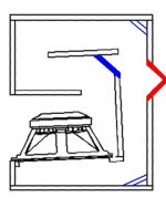
A more dramatic approach would be generating extra volume at the outside. Maybe not very practical but you could make it perfectly fit with center frequency and outlines for the working limits (changing Q).
(now you can also see where the idea came from... the extra volume in corners and their corresponding frequencies in the upper band") )
)
(now you can also see where the idea came from... the extra volume in corners and their corresponding frequencies in the upper band
)Attachments
Last edited:
Although Brian’s "dogfood" method seems to work it also seems to have a negative side effect; lowering gain/efficiency at LF.
I haven't tested it yet, but it should be possible to get some of this back by narrowing S1 -S3 (try it in HornResp). A possible side effect of this might be an overall change in response that has the notch partly returning, but again, it remains to be tested.
When you narrowing the horn’s path bigger then 1/6 of its dimension it clearly looses its efficiency.
My measurements suggest that this "loss" occurs at the lowest end of the passband and seems to coincide with a reduction in Fc. Narrowing S1-S3 should address this.
Instead I’m wondering about expanding the hornpath at problem areas.
The problem area you've identified in your diagram is incorrect. The DFD is actually located at bend #3 (starting from S1), not bend #1.
Another idea I had to deal with the notch was to include a resonater at that point (by basically adding a false bottom to the horn with an opening of suitable size that opens into bend #3), but I didn't know how to sim that, and it would increase overall volume, which might be better spent making the horn larger
.The problem area you've identified in your diagram is incorrect. The DFD is actually located at bend #3 (starting from S1), not bend #1.
Whoops - no, you're correct - I forgot that I tend to look at the THAM design with the driver on top, not below..
Hi Brian, by narrowing S1 – S3 you are changing the whole concept so “possible overall change” sounds more likely or do you mean narrowing S1-S2?
I’m not sure but I think your duct will also work as an air resistance point where it changes the mass of the air rapidly. It’s smaller then just 1/6 of the path which seems to be the number where LF efficiency reduction becomes noticeable.
I agree that Fc doesn’t change. If it would change it is more likely it will lower Fc as result of higher air mass. Actually, that’s what I was expecting from your duct, lower efficiency at LF but a less steep drop off. But maybe you need power to see that happening. That’s why I’m very curious to see your new duct test with high power also. It wouldn’t surprise me if the efficiency at max power at LF even drops further then with 1w/1m measurements..
Hi Brian, by narrowing S1 – S3 you are changing the whole concept so “possible overall change” sounds more likely or do you mean narrowing S1-S2?
Narrowing there may work as well.
I agree that Fc doesn’t change.
Actually it does. In my POC case, it was shifted down to 39 Hz.
If it would change it is more likely it will lower Fc as result of higher air mass. Actually, that’s what I was expecting from your duct, lower efficiency at LF but a less steep drop off.
That's what I noticed. However, the effect doesn't seem to be due to power compression issues, as when I tested at higher levels, the FR didn't seem to change much, if at all.
Note: I don't know if the duct size I chose is the optimum size. I basically pulled that size out of a hat - my intention was to determine first if the measured response with the duct I chose matches the sim, optimize the sim, then adjust the duct to match the optimization. As it goes, it seems I was quite lucky with the initial duct size
.I didn't mean loss by power compression, but it wouldn't surprise me if you use enough power the mass of the air even gets higher at an extra cost of efficiency at LF's. It should have looked like power compression but it's not the same. But it's a matter of enough power and I have no idea where this point will be.That's what I noticed. However, the effect doesn't seem to be due to power compression issues, as when I tested at higher levels, the FR didn't seem to change much, if at all.
Btw, I'm also wondering if the shape of your duct opening can make a (small) difference. Maybe this way you can change the effects a little between different parts within the bandpass.
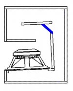
If it were my cabinet, I'd try adding a small restriction on the last horn part above the speaker.1meter 1/2 wavelength has a corresponding frequency of 172Hz, just where the dips is...
What do you guys think?
Clamp a 20mm, 40mm, 80mm etc. wide piece in there and measure the results.
No cabinet damage if it does not improve the response, and the test should only take a few minutes.
Unfortunately, if the "fix" corrects the dip, it will probably also add a peak somewhere else
.Art
If it were my cabinet, I'd try adding a small restriction on the last horn part above the speaker.
Clamp a 20mm, 40mm, 80mm etc. wide piece in there and measure the results.
No cabinet damage if it does not improve the response, and the test should only take a few minutes.
Unfortunately, if the "fix" corrects the dip, it will probably also add a peak somewhere else
Art
I tried something like that when I was messing around with the DFD. Any difference it made was a net negative. I actually tried at various locations around the horn before deciding on implementing it at bend #3. It was then I discovered that apparently the best way to find the best location was to use a mike and run it inside the horn to identify the point where the response peaks at the same location as the dip in the horn's output.
Art, as I explained earlier I don't like to use objects that (can) cause air resistance points in the pathway that we carefully calculated and optimized, that doesn't make sence to me. I prefer to go the other way around by creating extra volume right on the target spots (1/2 wavelenght from S1). To me that looks more logical and less destructive to the system then 'squeezing' the path together at some point.
If your cabinet was perfectly optimized, it would not have dips and peaks, right?Art, as I explained earlier I don't like to use objects that (can) cause air resistance points in the pathway that we carefully calculated and optimized, that doesn't make sence to me. I prefer to go the other way around by creating extra volume right on the target spots (1/2 wavelenght from S1). To me that looks more logical and less destructive to the system then 'squeezing' the path together at some point.
The entire TH construct creates "air resistance in a pathway".
Getting those pathways tuned to do what you want them may require a little thinking outside the box, "fuzzy logic".
If what I suggested works, you will make sense of it.
If my educated guess is wrong, and it does not work, you will be out a few minutes of time.
Then, like Spock, you can tell me my idea was illogical, and know for sure it was illogical
Art
Wrong, peaks and dips in a THs are caused by the TH's system. These show up perfectly in HornResp or Akabak. After build, the difference in peaks and dips are mainly caused by errors in the design.If your cabinet was perfectly optimized, it would not have dips and peaks, right?
Depends on how you look to it. But I can imagine that including new 'errors' sounds a little odd instead of logical. Look to the similarities with the extra volume in corners (that we accept as no problem in most cases) and how can this influence the output.Getting those pathways tuned to do what you want them may require a little thinking outside the box, "fuzzy logic"
Yeah, it's like you burn your bottom and afterwards I can state; "See Art! If you had asked I could have told you so... "If what I suggested works, you will make sense of it.
If my educated guess is wrong, and it does not work, you will be out a few minutes of time. Then, like Spock, you can tell me my idea was illogical, and know for sure it was illogical
Actually the truth is, if Brian didn't came up with his "dogfood Method" and beeing sceptic about how corner bracing can influence upper frequencies (months ago), I wouldn't have thought about expansion. While I was working on a theory behind corner bracing and the effects of the extra volume in corners the idea of using expansion became kind of logical to me. So when I used the word logic I was more referring to Brian's earlier try and the discussion about corners, then trying to be Spock for you afterwards, sorry for that...
After build, the peaks and dips predicted in Hornresp should be less than predicted. Differences in frequency between the dips and peaks reflect differences in the sim to the build.Wrong, peaks and dips in a THs are caused by the TH's system. These show up perfectly in HornResp or Akabak. After build, the difference in peaks and dips are mainly caused by errors in the design.
Depends on how you look to it. But I can imagine that including new 'errors' sounds a little odd instead of logical. Look to the similarities with the extra volume in corners (that we accept as no problem in most cases) and how can this influence the output.
Yeah, it's like you burn your bottom and afterwards I can state; "See Art! If you had asked I could have told you so... "
Actually the truth is, if Brian didn't came up with his "dogfood Method" and beeing sceptic about how corner bracing can influence upper frequencies (months ago), I wouldn't have thought about expansion. While I was working on a theory behind corner bracing and the effects of the extra volume in corners the idea of using expansion became kind of logical to me. So when I used the word logic I was more referring to Brian's earlier try and the discussion about corners, then trying to be Spock for you afterwards, sorry for that...
Errors in design?
What errors are introduced when a TH build designed as a straight circular design is converted to a rectangular folded design?
How much less time could be spent trying an easy non-destructive modification than defending a position
?Art
Last edited:
Yes, although I think that it is possible that some ‘equalisations’ of the dips can be caused/amplified by the ‘errors’ (extra volume) in corners.After build, the peaks and dips predicted in Hornresp should be less than predicted.
Not sure what you mean but I see it as two kinds of dips/peaks. One is part of the design and the other kind are the result of errors in the build. In case of the THAM the 170Hz dip is part of the design as it shows up in the prediction. The wider dip measured from a real cap is probably the case of irregularities between the theoretical model and the real cab.Differences in frequency between the dips and peaks reflect differences in the sim to the build. Errors in design?
Actually that is one of the most intriguing questions to me. If we could explain them all it means all theories are understood so we maybe can improve our designs in an earlier stage. That’s why I accept every personal failure in favour of. This means I appreciate any failure of others as much as my own or 200 feet walks by an ‘old’ man.What errors are introduced when a TH build designed as a straight circular design is converted to a rectangular folded design?
Lol, oh believe me... very much! But I guess I don’t take things personally so I don't have to defend my position ;-).How much less time could be spent trying an easy non-destructive modification than defending a position
Last edited:
Oliver,Yes, although I think that it is possible that some ‘equalisations’ of the dips can be caused/amplified by the ‘errors’ (extra volume) in corners.
Not sure what you mean but I see it as two kinds of dips/peaks. One is part of the design and the other kind are the result of errors in the build. In case of the THAM the 170Hz dip is part of the design as it shows up in the prediction. The wider dip measured from a real cap is probably the case of irregularities between the theoretical model and the real cab.
Actually that is one of the most intriguing questions to me. If we could explain them all it means all theories are understood so we maybe can improve our designs in an earlier stage. That’s why I accept every personal failure in favour of. This means I appreciate any failure of others as much as my own or 200 feet walks by an ‘old’ man.
Lol, oh believe me... very much! But I guess I don’t take things personally so I don't have to defend my position ;-).
Who you calling old?
I plan to live to be 125 years of age, I’m just getting started
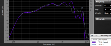
.Just noticed the upper response changed quite a bit in my Keystone TH cabinet between the clamp test and the build.
The differences as far as I remember was the addition of a 3/4 inch by 2 inch front panel cleat the width of the cabinet (about a 7% reduction in area), two front panel braces, each about 3 inches, and I also rounded the inside and outside of the opening.
The out of band loss is of no consequence for my use, but a seemingly small difference may have a larger effect than you might think it would.
I'll bet you a beer the little test I suggested before will help fill in the response dip.
You'll have to collect in New Mexico if I'm wrong, though
.Art
Attachments
Did Oliver call you old, Art?! Shame on Oliver! But before we accuse an innocent man I like to fresh your young mind, Art. As far my mind goes, or it must be my Alzheimer, I have not stated you can’t influence upper frequencies with smaller objects, on the contrary. From the beginning I stated relative small corner bracing can influence upper frequency parts.
The reason I don’t like the idea of objects in the pathway for dip correction is because they can influence the system too much and on different spots within the bandpass.That means a lot of extra variables that you are introducing by doing so. I don’t know how far Brian is in his attempt to imply narrowing in HornResp and Akabak but it seems both programs have difficulties to imply such thing for some reason. That’s why I have reasons to believe that expansion on hot spots might (also?) work. This expansion, proven by corners, seems to have less destructive side effects. It would not surprise me if it is also easier to imply in HornResp and Akabak.
In your case offering upper band response isn't a problem but the subject here is about improving Tham’s bandpass up to 250Hz and maybe 300Hz, if possible.
But you have proven your point Art and I don’t so I only can say cheers to that!
! But before we accuse an innocent man I like to fresh your young mind, Art. As far my mind goes, or it must be my Alzheimer, I have not stated you can’t influence upper frequencies with smaller objects, on the contrary. From the beginning I stated relative small corner bracing can influence upper frequency parts. The reason I don’t like the idea of objects in the pathway for dip correction is because they can influence the system too much and on different spots within the bandpass.That means a lot of extra variables that you are introducing by doing so. I don’t know how far Brian is in his attempt to imply narrowing in HornResp and Akabak but it seems both programs have difficulties to imply such thing for some reason. That’s why I have reasons to believe that expansion on hot spots might (also?) work. This expansion, proven by corners, seems to have less destructive side effects. It would not surprise me if it is also easier to imply in HornResp and Akabak.
In your case offering upper band response isn't a problem but the subject here is about improving Tham’s bandpass up to 250Hz and maybe 300Hz, if possible.
But you have proven your point Art and I don’t so I only can say cheers to that!
Last edited:
I don’t know how far Brian is in his attempt to imply narrowing in HornResp and Akabak but it seems both programs have difficulties to imply such thing for some reason.
Not quite true. The effects of the DFD mod for the THAM can be modelled in Akabak - I think Oliver put together the model for my POC which shares the same topology, and my measurements are a very close match for the model.
It's the effect of the DFD on my POC TP that we're getting difficulties with. I'm inclined to believe that the difficulty might be with my measurements, not the model, so I aim to repeat them as soon as I can.
Thanks for clearing that up Brian, I used the word 'seems' since it wasn't fully clear to me what the problem was. Do you think it is also implementable in HornResp?
Nope - HornResp doesn't have the ability to model the effect of a sharp restriction in the horn. To do that, it will need the ability to model at least 4 additional "steps" between S2 and S4.
- Home
- Loudspeakers
- Subwoofers
- THAM15 - a compact 15" tapped horn