Greetings,
First of all, a big "thank you" to you, Brian Steele, for putting in the effort and man-hours into this spreadsheet
A few... requests or tips, however you wanna call'em, though:
- Maybe put some short descriptions of the dimensions to their right (the current names are a bit... interpretable. I mean, to me, it sounds like "mounting width" would be the driver mounting hole diameter, and the "frame width" would be the outside diameter of the frame. On the sketch, i can only get a speaker-looking thing if the "mounting width" is about twice the numerical size of the "frame width")
- Maybe include an "operating manual" on a second sheet within the .xls, for greater ease-of-access
I mean, to me, it sounds like "mounting width" would be the driver mounting hole diameter, and the "frame width" would be the outside diameter of the frame.
That's correct.
On the sketch, i can only get a speaker-looking thing if the "mounting width" is about twice the numerical size of the "frame width")
Yup, a bug. Looks like I was using frame radius instead of frame diameter in my plot calculations for the driver. I've fixed this in the attached spreadsheet.
Attachments
That's correct.
Yup, a bug. Looks like I was using frame radius instead of frame diameter in my plot calculations for the driver. I've fixed this in the attached spreadsheet.
Grrr - forgot to turn back on some of the plots...
Attachments
Hmmm... I think some numbers are still slightly fudged in the driver sizes section...
Using the dimensions from this driver, i'm getting some "unnatural" driver shapes in the sketch
Using the dimensions from this driver, i'm getting some "unnatural" driver shapes in the sketch
The problem was two fold. The over sized panels which I didn't notice until I tried to get the last one (the baffle board) to line up correctly. When it didn't I just went off of the graph you posted on your web page.I didn't think the panel length errors would cause to much issues. Panel F was about 1~2mm too long and Panel I was about 5mm too long. There are some approximations involved with Panel F's position, so it's best to lay out the rest of the horn, then use Panel F to join Panel G to Panel A.
In it there is only ~4.8cm at the throat.
The graphs in your actually spread sheets are a lot better, so this shouldn't be a normal problem.
The possible panel length errors are an easy fix. You could make it a non-issue by posting the vertical and horizontal distances to define the first corner in space. As you are already checking those lines it shouldn't be a big deal to add in a box to list them. The extra length on the exit is not that big a deal.
Last edited:
Hmmm... I think some numbers are still slightly fudged in the driver sizes section...
Using the dimensions from this driver, i'm getting some "unnatural" driver shapes in the sketch
Yeah, it looks like I fixed the wrong dimension. Ok, fixed the right one this time. See attached (v 1.3.2)
Attachments
The problem was two fold. The over sized panels which I didn't notice until I tried to get the last one (the baffle board) to line up correctly. When it didn't I just went off of the graph you posted on your web page.
In it there is only ~4.8cm at the throat.
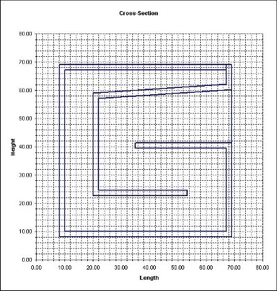
Yeah, something's not quite right with that graph. I've corrected it, thanks. The dimension at the throat should be 6.5 cm, not 4.8 cm. It looks like that version of the spreadsheet shifted the internal panels 1.7 cm (or one panel thickness) too high in the graph. The TH as built measures 6.5 cm at that point. The attached image is a closer match to what was actually built.
I made a few other errors with that build though that I'm not happy about, so I'm going to redo it next week. POC #2 part deux
Attachments
Hi Brian
I've been messing around with the latest and greatest. It seems it will fold a bowtie type unhorn. I think it is doing what it should. I still have to work out the driver dimensions to make it look like a driver! But have you ever come a long way in user friendliness. Much more intuitive.
I'll throw in a couple more types of tapped horns into the mix and post some screen shots to see what you think.
Mark
Hi Brian
I've been messing around with the latest and greatest. It seems it will fold a bowtie type unhorn. I think it is doing what it should. I still have to work out the driver dimensions to make it look like a driver! But have you ever come a long way in user friendliness. Much more intuitive.
I'll throw in a couple more types of tapped horns into the mix and post some screen shots to see what you think.
That's curious, because it was designed with only one particular folding in mind, the idea being that I'd add additional worksheets to the workbook to cover other types of foldings (I might take a try at JBell's folding next, once I sort out the bugs with this one).
I ran into another bug with the optimization routine last night. Seems it only likes boxes with square cross-sections. Going to have a look at that later today.
Unfortunately vacation ends from tomorrow and they're calling me from work already, so I may not have a lot more time to devote to this project.
I've attached an example of what the spreadsheet looks like with the parameters for my POC #2 (with the correct dimensions for panels E and I). "L3" shows the predicted length of the horn, which is a very good match for my measurements. Some fudging aroudn with d and h suggests that I'll have to increase them to just over 60 cm to get the effective path length to the target of 245 cm. I might try that for my next POC
Attachments
Hi Brian
I'll say it like I think it.
Anything that is as usefull and as well intentioned and thought out as this spread sheet is worth waiting for. If you want to push it along so that horns can be folded all the more power to you. I for one really appreciate it. And I will wait however long is required to see what you consider a finished product. Folding a horn into the most compact shape is one of the greatest chaalenges left to the designer. I'd happily pay you for a spreadsheet that helped that process along.
Mark
Version 1.4.0:
1. No longer restricted to square cross-sections (fixed that bug!).
2. Various bugs fixed with panel length calculations (internal panels).
3. Optimization now centered around initial horn expansion, target Length (L) and target mouth area (S4). Plot of cross-section will now go red if negative expansion is detected in the folding.
4. New graph showing horn expansion in the suggested folding.
Attachments
Amazing work!
This is how I found works for me after a bit of fiddling.
Set w to the desired depth of the horn (seen from the blueprint)
Goalseek Dcheck to 0 by changing Delta
Goalseek L(a,c) to desired length by d
Goalseek S4 to desired s4 by h
Repeat until it matches fairly well.
Could this be turned into a macro?
Repeat it 10 times or so.
Amazing work!
This is how I found works for me after a bit of fiddling.
Set w to the desired depth of the horn (seen from the blueprint)
Goalseek Dcheck to 0 by changing Delta
Goalseek L(a,c) to desired length by d
Goalseek S4 to desired s4 by h
Repeat until it matches fairly well.
Could this be turned into a macro?
Repeat it 10 times or so.
w actually represents the width of the horn, but the goal-seeking should work (within limits) with any of the three dimensions: d, w and h.
I haven't investigated if it can be turned into a macro. I want to get the math sorted out first
Does Mounting Depth include Magnet Height in the Cross Section chart?
That correct. You can check the results by looking at the dimensions suggested in the plot of the driver.
Version 1.5.0:
1. More bugs fixed with internal panel length calculations (sigh).
2. Added the ability to plot (highlight) the different sections of the horn
3. Added the ability to vary the flare rate throughout the horn (based on ratios to the initial rate).
If I have some time tomorrow (and if no more bugs show up), I'll include some braces in the parts list. The question though is how much bracing can I add (and where) before the response of the horn deviates too much from HornResp predictions...
Attachments
Are you basing the naming on viewing the TH with the opening facing towards you standing up?
To me it should be based how you see the drawing.
Height is height in the graph
Width is length in the graph
Depth is perpendicular to your screen.
Maybe you could add some notes and explain whichever way you go with red triangles.
Not sure how much bracing really changes things.
However something like this should suffice for most.
http://www.martinsson.cc/blog/images/THAM15-02.jpg
Are you basing the naming on viewing the TH with the opening facing towards you standing up?
That's correct.
Not sure how much bracing really changes things.
However something like this should suffice for most.
http://www.martinsson.cc/blog/images/THAM15-02.jpg
I'm planning to implement something quite similar to that. Would Akabak model the effects of such bracing?
- Home
- Loudspeakers
- Subwoofers
- Spreadsheet for Folded Horn Layouts...