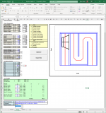
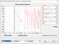
Well, that didn't take long. I've just uploaded another BOXPLAN that does a 6th order parallel bandpass sim based on a box design similar to one of the Paraflex designs. I opted to leave out the last bend in the rear path. The predicted results look very similar to what are being achieved with the Paraflex designs.
And along the way I found a possible way to improve the Paraflex design that looks similar to this layout. Something that would improve the phase response well up into the high midbass frequencies. All theoretical, of course....
And along the way I found a possible way to improve the Paraflex design that looks similar to this layout. Something that would improve the phase response well up into the high midbass frequencies. All theoretical, of course....
Attachments
Brian,
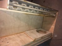
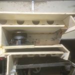
Is it possible to use MLTL3 (or another of your worksheets) to get the HR inputs for an enclosure like this one, where the 3 main segments are all straight but different widths?
Eric
Unfortunately, no. But it should assist in helping to lay out the internal panels in a box that size if you want a smooth transition from the start of the line to the vent.
Well, that didn't take long. I've just uploaded another BOXPLAN that does a 6th order parallel bandpass sim based on a box design similar to one of the Paraflex designs. I opted to leave out the last bend in the rear path. The predicted results look very similar to what are being achieved with the Paraflex designs.
And along the way I found a possible way to improve the Paraflex design that looks similar to this layout. Something that would improve the phase response well up into the high midbass frequencies. All theoretical, of course....
I like how that enclosure looks and the simplicity of the front and rear chambers are the 2 ports like a TH.
Failed to improve paraflex. That exact thing has been in my garage for almost a year. I really wish you would help people help, instead of blow torch your own path to guesses on your computer.
pOC used to be your teaching and learning machine. you need to build a paraflex from scratch before any more of this makes any less sense. Your onto the right idea, but you skip the reason along the way. People already know what are showing, plus MOAR. We just need you to show it. I dont think you realize this? Im sorry if i sound rude, but i cant help you pay attention. so do it on your own if you must. But you're gonna skip
The short cut of already been done to find out and accomplish? I dont see it?
That 110hz notch, is that a summation artefact before the shorter path takes over? Nice work either way, doubt it will be noticable irl, I really like the simplicity, build coming up?
Yes!!
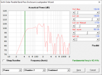
...and here's how they compare - similar box sizes, but entirely different shapes, to get an Fb around 42 Hz. The BP6P box is slightly larger, by about 20 L.
Im
Sorry, but that is wrong and i dont think you realize why? Fold it at harmonics. for once. Pretend the sim
Is missing the fold. Because it is. Now tell us the ‘fake’ results... and ask if its real. It is. Build it as a POC and you get most of what im
Saying. Please listen it will not disappoint. If you want sciense, here it is.
Last edited:
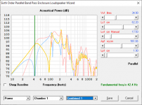
That 110hz notch, is that a summation artefact before the shorter path takes over?
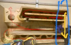
The situation is a bit more complicated than that, as both paths are contributing to the response above 100 Hz (see attached image, showing the output from each vent - the output from the rear path is highlighted in yellow and the output from the front path is highlighted in blue). It should be possible to tweak the design to get rid of the minor notch (some experimenting with adding a stub at the start of the rear path seems to produce this result).
Nice work either way, doubt it will be noticable irl, I really like the simplicity, build coming up?
Yes, box losses will make the notch a lot less noticeable. And bear in mind that the sim does not take into consideration Vtc, Atc, bracing, box losses or the impact of the driver's chassis sitting in the front path.
I'm not sure that I will eventually build this though - the requred shape of the box makes it a bit more difficult to transport, particularly in my vehicle, whose trunk favours long rectangular boxes rather than squat and square ones of the same volume.
Attachments
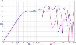
...and here's what the response of the equivalent offset TL looks like (i.e. if you remove the front path). There is a general 2dB increase in sensitivity across the passband. The box is just over 40% bigger however. Fb does shift up a little, I'm not sure why.
Attachments
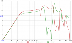
...and here's what the response of the equivalent offset TL looks like (i.e. if you remove the front path). There is a general 2dB increase in sensitivity across the passband. The box is just over 40% bigger however. Fb does shift up a little, I'm not sure why.
Neither do i, until i fold it.
draw this? and use a driver worth predicting or assuming
18 ds 115. Skar 12 ddx d2 (x2)? Almost the same animals
Im Sorry, but that is wrong and i dont think you realize why? Fold it at harmonics. for once.
Any aberration between the predicted response and the actual response due to folding is likely going to happen above, and perhaps way above, the useful bandwidth of this particular alignment.
For proof, look at the measurements on my project page for POC3. That has some pretty long folded sections and the impact appears above 200 Hz - for a build designed to be used below 120 Hz. Same for the POC4, a much larger TH built with the B&C 18TBX100 in mind.
Apart from box dimensions and the dimensions of the folds, another contribution to the differences at higher frequencies are going to be the differing path lengths around the bends. You can actually work out at what frequencies the impact of those bends might show up - measure the shortest path around a bend, the longest path around the same bend, subtract one from the other, then multiply by two - that's the wavelength of the frequency where you're likely to see a dip in the response. (BTW - this is probably one of the main reasons why you'd want to avoid having a large bend at the last section of a bass horn
") )
)Neither do i, until i fold it.
I suspect the answer is simpler than that - perhaps David included the impact of end effects in the BP model but not in the OD model. Those would tend to shift Fb downwards as the effect increases the effective length of the vent.
Perhaps David can confirm....
We are talking harmonics here. An aberration is not the same if its coming from a source thats mathematically a harmonic of the other.
That will represent itself in reality. I have the POC for that. imo 3/4 of it. I thought you were going to bump into it too, but you altered the course because you require a certain shape.
120cm/120cm folded/(split) by a tapped entry and then 120cm folded and 120cm. This is also 80 cm.... and 320cm. maybe the answer is 80/80, but it seems no fundamental establishes a decent hz for a subwoofer. (35.8hz is 240cm. 2x twice. And 90 degrees in phase twice. Or 45 4x...from 71hz and so on 71 is 107,214.... these all must remember the Zero phase at 20 something...and begin from there
If taped or compounded or offset, etc or theyre just loosing the ‘sealed box’ benefit.
Its not wrong of its spun back to right. We are spinning both sides of a drivers output. zero and 360 or 180 and 180. Its still in phase to us.
90 fold 90 driver 90 fold 90 driver.
Whats phase? At start and end? A circle. Whats a tapped circle or two phase sine wave split in the muddle of the others start?
3 phase AC current tskes this to another extreme, but we have ‘tapped’
Last edited:
I've uploaded an updated version that's supposed to be compatible with both 32-bit Excel and 64-bit Excel. V0.2 BETA. Let me know how it works.
i deleted it and downloaded the new version
same thing im going to try my desktop pc and see
ill met you know asap
Brian,
Is there somewhere that I can find an explanation of the methodology you are using to segment folded horns and determine the HR parameters to represent them?
I feel like I get the basic concept of what you are doing by looking at your excel spreadsheets, but I can't quite infer what exactly the "rules" are that you use to draw the lines that break up the enclosure. Also, it's not clear to me always which line or lines it is that you are using for the basis of the HR parameters.
At bends in the line I see you are drawing lines at nearly 0/30/60 and 90 degrees, but how are the actual angles determined? Are the S2, S3, and S4 areas based on the lengths of the lines at (nearly) 0 and 90 degrees? And what about the segment lengths? Do those also only start and end at the (nearly) 0 and 90 degree lines?
It looks like you are using the "Advanced Centerline" method, but exactly what the rules of that method are is not 100% clear to me.
Thanks,
Eric
Any aberration between the predicted response and the actual response due to folding is likely going to happen above, and perhaps way above, the useful bandwidth of this particular alignment.
For proof, look at the measurements on my project page for POC3. That has some pretty long folded sections and the impact appears above 200 Hz - for a build designed to be used below 120 Hz. Same for the POC4, a much larger TH built with the B&C 18TBX100 in mind.
Apart from box dimensions and the dimensions of the folds, another contribution to the differences at higher frequencies are going to be the differing path lengths around the bends. You can actually work out at what frequencies the impact of those bends might show up - measure the shortest path around a bend, the longest path around the same bend, subtract one from the other, then multiply by two - that's the wavelength of the frequency where you're likely to see a dip in the response. (BTW - this is probably one of the main reasons why you'd want to avoid having a large bend at the last section of a bass horn
Okay, let me look over you POC in more detail. I haven't read them in a year or so when i first started all this stuff.. and those details would have illuded me
Meanwhile, tell me what i all about my current POC. And the 12-24 along the that might suggest theres something here thats only 3/4 acomplished. and adding a fokded sengment or sneaking it into a last segment is the ‘thing’ if using the driver thatll push that much
Im trying to show you something youre not seeing and i am
Failing to explain it well. This us my fault, and i promise to figure out a better thats not dumping a huge pile of math or notes or sims or the actual cabinets and results to just be more confusing. I am Confusing, so i must work around conveying the idea that this is harmony, not harmonics. Thats in seies and in patallel or all of them
Paths around bends are not foreign to us.
Attachments
Last edited:
Im getting dumber ever time...
But that all let to comfused..
The 12 versions im between or round pipe, round bend and Straight TLs....
its not ‘smart’ that can be found, its only confused.
Its not my first rodeo cowboy. its my first time knowing what to REALLY ask others... because i realize what ive missed along the way
Do the math. Or split the sim. either way were both wrong until until
We agree on the midband as the middle of a path from center. Tap the center of a small vas powerful Drivers path to longer things
Attachments
Last edited:
- Home
- Loudspeakers
- Subwoofers
- Spreadsheet for Folded Horn Layouts...