"Has anyone read the AES paper by Don Keele Maximum Efficiency of Direct Radiator Loudspeakers? "
Yes a long time ago when I had hair.
And I concur with djk. Full sized horn in normal interiors are a waste of space!
Hi Art,
Thanks for your comments.
I am not sure that getting more sleep is going to help much at this stage...") .
.
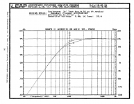
I have just been looking at an AES paper which contains graphs showing the SPL of one speaker compared to fifteen speakers connected in parallel, driven by the same voltage. The charts are predictions, but are very close to actual measured values which are also given in the paper. The results are quite different to those generated using any of the three Hornresp models currently under consideration, and don’t comply with the coherent signal summing rules discussed earlier.
The first chart attached shows the SPL for one speaker. The second chart shows the SPL for fifteen speakers. The difference between the two at higher frequencies is 13 dB, much less than the summing rules would suggest should be the case.
Until I can find a more robust model to better predict the performance of multiple speakers, I think that it is probably safer to leave Hornresp as it currently is.
Kind regards,
David
Thanks for your comments.
I am not sure that getting more sleep is going to help much at this stage...
.I have just been looking at an AES paper which contains graphs showing the SPL of one speaker compared to fifteen speakers connected in parallel, driven by the same voltage. The charts are predictions, but are very close to actual measured values which are also given in the paper. The results are quite different to those generated using any of the three Hornresp models currently under consideration, and don’t comply with the coherent signal summing rules discussed earlier.
The first chart attached shows the SPL for one speaker. The second chart shows the SPL for fifteen speakers. The difference between the two at higher frequencies is 13 dB, much less than the summing rules would suggest should be the case.
Until I can find a more robust model to better predict the performance of multiple speakers, I think that it is probably safer to leave Hornresp as it currently is
.Kind regards,
David
Attachments

Last edited:
Keep your chin up David!
Rules!
They are usually only applicable under very narrow circumstances. What you are trying to cover is real life situations. I think I have seen that paper to. I have a set of three three inch thick binders that are buried up in my attic that I did most of my studying from back in the 80's. If I only remembered half of what I read I'd be somewhat intelligent!
Not as easy as it looks. Hence the rules tend to become rather simplified. Art's observations and Wayne's are most helpful. Djim graphs are priceless.
That you are narrowing down on what really matters is kind of obvious. The math involved is not that obscure. You have cracked tougher nuts before David.
The empirical evidence points in the direction that the current model is wrong. What there seems to be missing is a consensus between the measurements. Your latest paper seems to be a source where it is under very controlled measurement methods. Maybe you have found the information that you are looking for?
Hi klampykixx,
I am more interested in the four hot "mag wheels", stacked to the left of the horns
Kind regards,
David
Hi david, they belong to my jeep. 15inch alloys. If you want to pm me theyre actually for sale.
This sounds completely noobish after reading this page, but if i can make a mount that utilises two twelve inch drivers in the same throat as a single fifteen, what effect would that have on the response?
and second, if i was to put the Jbell horn in a car, would extending the horn path be of any benefit? I tried one in my wagon and it just wasnt that impressive.... are horns any good in cars?
One to 16 speakers should be +15, I read about a 12 dB difference in the 1986 Leap version 2.10 simulation, which would be sort of consistent with an incoherent summation and one less(15 instead of 16) speaker.Hi Art,
Thanks for your comments.
I am not sure that getting more sleep is going to help much at this stage...
I have just been looking at an AES paper which contains graphs showing the SPL of one speaker compared to fifteen speakers connected in parallel, driven by the same voltage. The charts are predictions, but are very close to actual measured values which are also given in the paper. The results are quite different to those generated using any of the three Hornresp models currently under consideration, and don’t comply with the coherent signal summing rules discussed earlier.
The first chart attached shows the SPL for one speaker. The second chart shows the SPL for fifteen speakers. The difference between the two at higher frequencies is 13 dB, much less than the summing rules would suggest should be the case.
Until I can find a more robust model to better predict the performance of multiple speakers, I think that it is probably safer to leave Hornresp as it currently is
Kind regards,
David
I have no problem with you leaving Hornresp as it is, it’s “close enough for rock & roll”
.I will continue to point out to the newbies that are counting on a low corner reduction in multiple TH that they will be disappointed
.Perhaps one day someone will actually measure 1, 2, 4 and 8 SH15 cabinets and we can see how they actually perform compared to the simulations people take for granted.
Art
There's definitely an effect (or set of effects) that cause bass to get more increase (or higher frequencies to get less increase) when grouping basshorns closely together. My thinking is it's one or more of these three things, or perhaps a combination of all of them:
1. Mouth size getting closer to acoustical scale at LF (causing an efficiency increase at LF)
2. Reduced summing at HF because of acoustic distance (causing phase/summing reduction at HF)
3. Shift in the movement of the acoustic center (causing distance to change as a function of frequency)
I had considered directivity increase, and it is still a possibility - definitely when groups become large - but I dismissed it in the measurements I posted earlier because the groups were still acoustically small in the passband. However, directivity isn't an on/off thing as size increases with respect to wavelength, it's a gradually increasing thing. So I suppose it may be responsible too, perhaps in part, but I do not think the three items I listed above should be dismissed.
The point is, outdoor measurements of basshorns regularly show more of an increase in the low half of the passband than the high half, even when the combined mouth size is acoustically small. It seems something of a coincidence that the shift appears to happen around the same frequency that the path length is 1/2λ. To me, this is a pretty clear indication that there is more going on than simple coherent summation of wavefronts.
Looks like Djim understood what I pointed out in #1339, undriven cabinets had a goofy effect on the FR of both the TH-115 and the Punisher cabinets.Hi Djim,
Post #1349: no, you don't.
Regards,
TH-115 normally don't have the peaks shown in the 1 and 2 cabinet model.
For accurate 1, 2, 4, 8 tests the cabinets need to be added one at a time, but for convenience they are often stacked all at once, then tested one at a time.
Unless the non-powered cabinets are shorted, odd peaks and dips will show up, as they did in Ivan's, Doober's and my test which was specifically designed to show the influence of an extra cabinet when shorted and unshorted.
I agree with Wayne's first two points regarding the reduction of HF and increase in LF of large FLH arrays:
"1. Mouth size getting closer to acoustical scale at LF (causing an efficiency increase at LF)
2. Reduced summing at HF because of acoustic distance (causing phase/summing reduction at HF)
3. Shift in the movement of the acoustic center (causing distance to change as a function of frequency)"
As far as the third point, I suspect the cabinet interaction in multiples, even though powered, still exhibits some of the "dummy cabinet" syndrome, diffracted upper frequency waves reflected off the adjacent mouth interiors have differing time delay from the original, reducing coherence (and level) in the upper response of the array.
If this theory is correct, an array of BR would have less of the upper frequency reduction, as the front plane is more similar to a solid baffle than horn cabinets are.
I wish I had Smaart when I had 8 FLH cabinets, some of the questions could have been answered with various stack configurations and placing covers over undriven shorted cabinets.
The last pair of FLH were sold recently, so I can't do those tests, though I do have 8 BR cabinets I could test in various configurations if there is any interest in comparison.
Art
Hi Oliver,
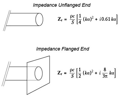
The difference between the values in 1/4 and 1/2 in the equation was clear to me.
What I find surprising is the difference in 'end correction' for the 1/4wl tube in the equation. I always thought this was equal for all 1/4WL resonators and not space/radiation depending.
That makes me wonder if the lowering if the low corner by stacking is based on the acoustic coupling of the 'end correction'? That could explain the much smaller drop in extension by stacking between model and measurement.
(edit: Hi Art, the peaks are not the problem, those are just a small 'mistakes' that are too obvious sticking out. It's the general pattern in the lines that looks similar to Ivan's findings and give a similar 'smooth' response in quad settings)
Last edited:
I agree that the environmental "loading" forms a condition that could be described as end correction, e.g. boundary loading and/or cabinet grouping. We see boundary conditions change the radiation impedance in a lot of ways, and many of them form a sort of end correction. Even vented speaker cabinets see this kind of thing, transmission lines and of course, horns. I think this is probably why the lower cutoff point shifts slightly downward when a horn is boundary loaded or used in groups.
About unpowered subs sitting next to ones being tested, that's a definite no-no, isn't it? There is little doubt that an unpowered sub in close proximity to a subwoofer being tested will have a strong effect. One would really hope to have the subwoofer out in a large open area, free from reflections and stuff that might resonate or act as bass dampers. I think that if these conditions aren't met, the measurement is pretty tainted.
The acoustic center is an interesting concept. It is defined as the point where sound appears to eminate. There are actually two acoustic centers, one that relates to amplitude and the other that relates to phase. The acoustic center with respect to amplitude is where radiated power is maximum, the point where inverse-square falloff begins. The acoustic center with respect to phase is where sound appears to originate, measured as time delay. These two points may or may not be the same, and they may or may not be at the voice coil of the driver. Usually, they are not the same place, and they almost always move with frequency.
Acoustic center offset is most noticeable when the measurement microphone is placed too close to the speaker under test. The further away the microphone is placed, the less of an affect the exact position of the acoustic center makes.
It's a matter of ratios - If the acoustic center shifts forward three feet as a sine is swept through the passband, it almost cannot be detected in measurements made thirty feet away. But measurements made only three feet away will definitely be affected.
- The Acoustic Center: How it applies to Loudspeaker Measurements
Sorry Wayne, my response in post# 1352 was probably clumsy formulated but I'll try it again and hope more people will respond.
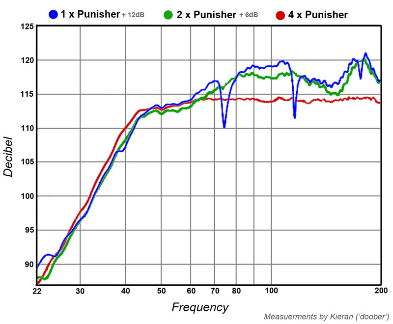
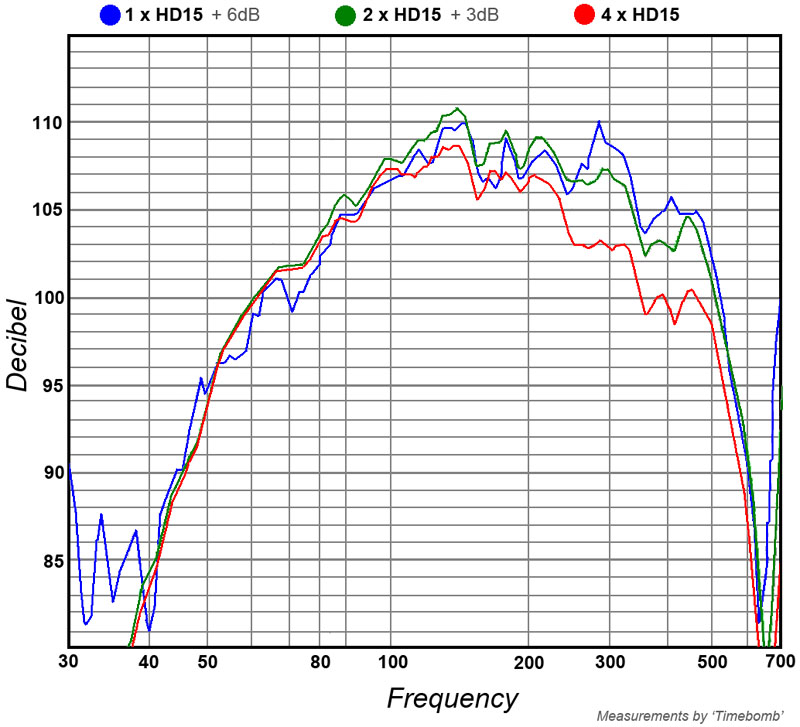
The drop of low corner as measured by Ivan Beaver at 3 Meter with four TH115’s and the drop measured by Kieran at 2 Meter with four of his FLH Punisher’s, are both far enough away from the 'end correction' in relation to my point. Both measurements show a very similar drop of the low corner in stacks. If their average SPL response is not correct in relation to their 10meter SPL response, is not much of an issue here and Wayne, you have measured a drop also at 10m with just 2 cabs.
If you use the 'end correction' of 1/4WL acoustics as tool for calculating the drop, the results look similar to what these people have measured. I don’t know what theory/formula HornResp is using now, but it looks like there is something wrong as mentioned by Art from the beginning.
Last edited:

Absolutely, that's my understanding too. I agree that the environmental "loading" forms a condition that could be described as end correction, e.g. boundary loading and/or cabinet grouping. We see boundary conditions change the radiation impedance in a lot of ways, and many of them form a sort of end correction. Even vented speaker cabinets see this kind of thing, transmission lines and of course, horns. I think this is probably why the lower cutoff point shifts slightly downward when a horn is boundary loaded or used in groups.
I also think there are other things going on, causing an additional increase in SPL between 1/4λ and 1/2λ and a decrease in SPL above that, for the reasons I listed in my last few posts. But I'm certain the frequency drop of the low corner is due to the same sort of thing we see in other areas of acoustics that are all basically this same "end correction" principle.
I also think there are other things going on, causing an additional increase in SPL between 1/4λ and 1/2λ and a decrease in SPL above that, for the reasons I listed in my last few posts. But I'm certain the frequency drop of the low corner is due to the same sort of thing we see in other areas of acoustics that are all basically this same "end correction" principle.
This sounds completely noobish after reading this page, but if i can make a mount that utilises two twelve inch drivers in the same throat as a single fifteen, what effect would that have on the response?
Hi klampykixx,
Use the Hornresp Driver Arrangement tool to specify the two drivers, and then check the predicted response.
Kind regards,
David
One to 16 speakers should be +15, I read about a 12 dB difference in the 1986 Leap version 2.10 simulation, which would be sort of consistent with an incoherent summation and one less(15 instead of 16) speaker.
Hi Art,
Just to clarify - how did you arrive at +15 dB for 16 speakers connected in parallel?
Based on the SPL summation information provided earlier, my understanding was:
Coherent summation:
1 to 2 = +6 dB
2 to 4 = +6 dB
4 to 8 = +6 dB
8 to 16 = + 6dB
1 to 16 = +24 dB
Incoherent summation:
1 to 2 = +3 dB
2 to 4 = +3 dB
4 to 8 = +3 dB
8 to 16 = +3 dB
1 to 16 = +12 dB
Are you perhaps assuming that the test signals being summed in this case would be partially coherent only?
Using the original Hornresp model for 15 speakers in parallel, the difference is predicted to be +23.60 dB at low frequencies and +11.77 dB at high frequencies. Interestingly, this is consistent with the speaker outputs being coherent at low frequencies, but becoming progressively less coherent at higher frequencies due to directivity interference effects.
1 to 15 coherent = 20 * Log10(15) = +23.52 dB
1 to 15 incoherent = 10 * Log10(15) = +11.76 dB
Incidentally - if any one is interested, the AES paper I referred to earlier is titled "Complete Analysis of Single and Multiple Loudspeaker Enclosures". The author is Chris N. Strahm.
Kind regards,
David
Hi Art,
An interesting statement about bass-reflex speakers, taken from the AES paper:
"At frequencies less than the port / box resonance, the small impedance produced by the mass of the port permits the impinging sound wave to radiate through the port into the box cavity as shown in figure 14. This causes identical pressure to exist inside the enclosure as exists on the surface of the enclosure. The result of equal pressure on both sides of the cone causes a cancellation of pressure and produces no net force on the cone. In this case the speaker does not "feel" the presence of other enclosures. Therefore, arrays of ported enclosures contain no mutual coupling at frequencies less than the port / box resonance."
I for one, would be very interested in any measurements that can be done with 8 cabinets.
As well as measuring the performance of the 8 bass-reflex cabinets connected in parallel and then in series, compared to a single cabinet, perhaps the ports could then be temporarily sealed to form closed back chambers, and the measurements repeated.
If the cabinets contain multiple drivers, then it may be better to power just the bass driver for the purpose of the tests, to avoid any complications due to cross-overs, etc.
Kind regards,
David
If this theory is correct, an array of BR would have less of the upper frequency reduction, as the front plane is more similar to a solid baffle than horn cabinets are.
An interesting statement about bass-reflex speakers, taken from the AES paper:
"At frequencies less than the port / box resonance, the small impedance produced by the mass of the port permits the impinging sound wave to radiate through the port into the box cavity as shown in figure 14. This causes identical pressure to exist inside the enclosure as exists on the surface of the enclosure. The result of equal pressure on both sides of the cone causes a cancellation of pressure and produces no net force on the cone. In this case the speaker does not "feel" the presence of other enclosures. Therefore, arrays of ported enclosures contain no mutual coupling at frequencies less than the port / box resonance."
The last pair of FLH were sold recently, so I can't do those tests, though I do have 8 BR cabinets I could test in various configurations if there is any interest in comparison.
I for one, would be very interested in any measurements that can be done with 8 cabinets.
As well as measuring the performance of the 8 bass-reflex cabinets connected in parallel and then in series, compared to a single cabinet, perhaps the ports could then be temporarily sealed to form closed back chambers, and the measurements repeated.
If the cabinets contain multiple drivers, then it may be better to power just the bass driver for the purpose of the tests, to avoid any complications due to cross-overs, etc.
Kind regards,
David
- Home
- Loudspeakers
- Subwoofers
- Single sheet TH challenge