Hey PASC,
Could you post the images instead of linking back to your host page? They have adds for adult stuff above your images. Use the link for your picture and the
Attachments

1W into one, two, or four TH.

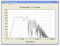
Why do I read contradicting statements all the time about multiples not pushing the "knee" a few hz lower?
You can clearly see in the sims that the way the knee falls off around 40hz is much lower with 4 cabinets then it is with only 1.
Is this just due to a smoothed response?
Yet some say this is true some say this isn't....
Last edited:
It depends if your TH array adds up to a propper mouth area. I find it to be effective.Why do I read contradicting statements all the time about multiples not pushing the "knee" a few hz lower?
You can clearly see in the sims that the way the knee falls off around 40hz is much lower with 4 cabinets then it is with only 1.
Is this just due to a smoothed response?
Yet some say this is true some say this isn't....
Attachments
Those of us that have actually measured single TH against multiples have found the low corner does not change as it does for FLH in multiples.Why do I read contradicting statements all the time about multiples not pushing the "knee" a few hz lower?
You can clearly see in the sims that the way the knee falls off around 40hz is much lower with 4 cabinets then it is with only 1.
Is this just due to a smoothed response?
Yet some say this is true some say this isn't....
Going from one to four cabinets with the same voltage drive gives a 12 dB increase in level, and the increased frontal area provides greater directivity, which can add even more level on axis.
Those level increases make it easy to think the low corner has gone lower, but so far I have not seen any actual measurements showing that to be the case.
Art Welter
Hi Art,the low corner does not change as it does for FLH in multiples.
Why do you think this is?
Sorry I'm not Art but I can explain.Hi Art,
Why do you think this is?
")
‘Traditional’ horns like Front Loaded Horns (FLH's) are designed in such way that the mouth area is smaller than optimum. We do design ‘traditional’ horns with a smaller than optimum mouth area to make them physically smaller so they become transportable.
By the acoustic coupling of several mouth areas of ‘traditional’ horns they become one large mouth area that is closer to its ‘ideal’ area. Because of this phenomenon you will see besides the drop of the low corner a further rise in amplitude of its low corner.
TH’s already have an ‘ideal’ mouth that is already in full conjunction with its system. Actually that is the point behind TH’s what makes them unique. That the mouth area is much smaller than those of ‘traditional’ horns is just a matter of a different working mechanism and a personal choice. In other words: if you design a traditional horn with an ideal sized mouth they would couple more or less the same as TH’s! (I stated more or less because its a little more complex but that isn't of major importance in this matter).
People that have worked with large stacks of FLH’s know that after a certain amount of units there is almost no drop in low corner any longer. With the old classical Fane horns that number was around 8 while the “Punisher” needs more then 12 to find to this point.
I’ll try to explain it in another way. If you build a physical extension for your TH (by the 0.6 diagonal concept) it will lower it’s low corner but will not give any extra dB to the output! If you build a physical extension for a traditional horn (by the 0.6 diagonal concept) the low corner drops AND you will see a rise in amplitude of the low corner.
You can easily model that in HornResp. Pick any TH and when you extend the total horn path after S4 (driver position) with factor 0.6 of the diagonal of the mouth (in other words keep S4 on the exact same position) and multiply the mouth area by 2, you will see a small drop of its low corner but no amplification at the low corner!
Now pick any FLH with a smaller than ideal mouth area (iow non full sized horns). When you extend the horn path length with 0.6 of the diagonal of the horn mouth and multiply the horn mouth area by 2 you will see a similar drop of the low corner but with a rise in amplitude at the low corner. This means the mouth area is getting to a better ratio with the system behind it.
Hopefully this clears up your question.
Last edited:
Hi Dan,I think the answer is if you do it right it works.
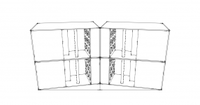
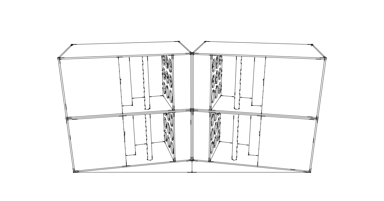
As an example I'll use the design I posted above as an example: 1@2.83v vs 4 @2v
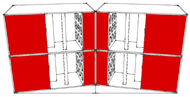
Some people noticed their TH in real live do measure lower and have an earlier roll off. The main reason is because of what you show us. Your ‘real’ cab isn’t represented by any HornResp plot . The red surfaces are not seen at all by HornResp and therefore a real measurement from such stack will look different.
What happens is you extend the radiating area (red surfaces) and therefore the "horn bubble". Also you extend the path physically by placing the cabs under a small corner from each other. In such example you will see in measurements your knee point drops while the roll off starts earlier as predicted. In other words your TH plays lower as predicted at the cost of an earlier roll off. This way of positioning can make up till a certain degree but I call that: 'tuning until you'll get the best response', which is a very good way the get the maximum efficiency from your system.
HornResp only shows what happens if the mouth areas are coupled without any space between them and no extra radiating surface is created. If you want to get close to the response from any HornResp, design your cab in such way there is a minimum of radiating surface. If you do so you will see the drop of the low corner after stacking, just like HornResp predicted.
Last edited:
"I can't recall the model number.."
Might that be the JBL 265H-1?
Neo magnet, I've seen it on eBAy for $172.
Transducer Power Rating (AES) : LF: 500 W (2000 W peak), 2 hrs
350 W (1400 W peak), 100 hrs
http://www.diyaudio.com/forums/subwoofers/186599-whats-up-3015lf-pricing-3.html
Might that be the JBL 265H-1?
Neo magnet, I've seen it on eBAy for $172.
Transducer Power Rating (AES) : LF: 500 W (2000 W peak), 2 hrs
350 W (1400 W peak), 100 hrs
http://www.diyaudio.com/forums/subwoofers/186599-whats-up-3015lf-pricing-3.html
Why do I read contradicting statements all the time about multiples not pushing the "knee" a few hz lower?
have found the low corner does not change as it does for FLH in multiples.
I thought we beated this horse to death a long time ago.The red surfaces are accounted for in the 4 cab sim.
Last edited:
Very niceThe red surfaces are accounted for in the 4 cab sim.
 indeed! I guess you really meant "if you do it right it works"
Yep, but I haven't seen it used before in a HornResp plot as most find the number of points in their HornResp already too limited.I thought we beated this horse to death a long time ago.
"I can't recall the model number.."
Might that be the JBL 265H-1?
Neo magnet, I've seen it on eBAy for $172.
Transducer Power Rating (AES) : LF: 500 W (2000 W peak), 2 hrs
350 W (1400 W peak), 100 hrs
http://www.diyaudio.com/forums/subwoofers/186599-whats-up-3015lf-pricing-3.html
The JBL 265H series driver was tried earlier and the user preferred the 3015LF as the JBL has a short x-max despite it's motor technology.
I thought we beated this horse to death a long time ago.
 apparently not enough, so I gave an example
 OK. Apparently not enough.
Marry Christmas- Home
- Loudspeakers
- Subwoofers
- Single sheet TH challenge