Hi Again,
I just want to add: if I had to build a version of the SS15, I would take the attached drawing add a few more corner reflectors in the upper corners, file around a little at the details for the front chamber (and the box width) in Hornresp, and give that a try.
Regards,
I just want to add: if I had to build a version of the SS15, I would take the attached drawing add a few more corner reflectors in the upper corners, file around a little at the details for the front chamber (and the box width) in Hornresp, and give that a try.
Regards,
Attachments
jbell: I have the feeling you started with a much bigger version, and pared it down until you got the the point of no return. You certainly kept us busy. Nice work.
Regards,
")
tb46; I mainly put them in to brace the box, knowing thay would not cause any restricshoins.Djim: I'm not going to touch the subject of corner reflectors, or whatever somebody wants to call it. Screamerusa reported his empirical results in the furybox thread, jbell added his practical experiences, and after studying the general area of discussion (over a long time period, front horns, back-loaded horn fullranges) I know less than I did when I started.
Thanks for looking into this for me. I had a sinking feeling when you said yours did not come out as good as my simulashoin.I looked at the Hornresp files for the SS15 and your modified version again, and found that the difference was mainly from slight changes in the way the original was done, and from the fact that I had not entered values for Vtc/Atc/Ap1/Lpt in the original. I redid the original using soho54's corner method, and added the same front chamber (right or wrong) in both models. They now are quite similar, with your modified version being slightly better in the 144Hz dip area. You'll have to enter the data into Hornresp to see the lines clearly. You can reduce the dips in that area by setting S1 to .01.
I was thinking of putting reflectors on the sides of the S1,S2 area in a "v" and making the width of the area 3.5" all the way. That would make the speaker mounting board stiffer, and you think it would help with the dips on the high end? thats a ++ if it will not effect the low end output.You can reduce the dips in that area by setting S1 to .01.
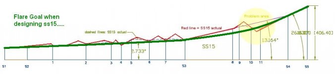
Can you get it to bend at S3?As to the purple line in the flare drawing (Post #559), it's just an attempt at showing the average of the respective tapers, kind of a general sanity check for the location of the Hornresp inputs (in other words: disregard if it gives you a problem).
I will be building next week, and pass along any changes for the record.To get this any better you will have to draw exactly what was build (which only the builder can do, as there are too many gaps in the dimensions), and use AkAbak.
Thanks again for all you time. Andy
Hi 4pyros,
"...Can you get it to bend at S3?..."
It can be done, but it's a bit of work. Here is just a quick look at it. After you make any modifications to the indicated panels you also have to work your way through the bends again, and transfer the result to Hornresp, and make modifications to the drawing, and so on.....
As to the S1/S2 area: screamerusa found it to be important to reduce S1, maybe take another look at the furybox. I think it can only help.
Regards,
Attachments
Last edited:
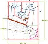
Hi Oliver,
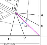
I made a small correction on your drawing to get the outlines of the SS15 inclusive the corner volumes (just a rough estimation actually). Is there any way you can calculate the exact volume differences between prediction and real cab in the area between reference points 9 to S4?
https://lh3.googleusercontent.com/_nSWmrMRpHJI/TXlQMEHl1dI/AAAAAAAAAMA/elFJd7yFk3o/TB_03.jpg
Hi Djim,
It's not as straight forward as it looks to get the respective volumes, e.g.: You may have noticed, that I like looking at the S4 dimension at right-angle to the centerline of the respective horn section in reference to the position of the cone, not necessarily the mounting position of the basket. Also, jbells explanation of his target flare makes a lot of sense. The purple line is just to check that I'm not too far off. Anyway, see the attachment.
Regards,
Attachments
Thanks Oliver,
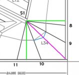
I think you forget something with your method. As long you don't introduce another reference point this goes straight into the corner you never get an accurate volume calculation (see purple line). That is my problem with this method. It also cuts of the path length a little (see blue line) although this is to small to be significant. So you wont see that back in your horizontal representation. If someone is going to use corner bracing from just above point 9 to a little after point 10 it will cut within the path. I hope my words make sense...
I think you forget something with your method. As long you don't introduce another reference point this goes straight into the corner you never get an accurate volume calculation (see purple line). That is my problem with this method. It also cuts of the path length a little (see blue line) although this is to small to be significant. So you wont see that back in your horizontal representation. If someone is going to use corner bracing from just above point 9 to a little after point 10 it will cut within the path. I hope my words make sense...
Attachments
Last edited:
Thats why I have two flare rates at the end to make it more exponential. So thare is one rate from S1 to S3, one from S3 to ref line #11 and one from thare to the end.considering straight boards is all that there is to work with...
when drawn right it looks quite elegant. Andy
The Blue line looks longer to me. seems like the more ref lines you put into a corner the more accurate the measurements can be. I only used one becuase I was hand drawing. Looking at the three you put in the last post seems the best way to measure. AndyIt also cuts of the path length a little (see blue line) although this is to small to be significant.
The other two important reference points I show you in green (90 degrees straight on the outline of the cab). If you integrate these 3 new reference points you will see in your horizontal representation why this is important. Maybe not in volume difference but sure when it comes to air resistance, I think.
In my opinion this is exactly the reason why corner correctors (deflectors whatever...) are so 'sensitive' to the real output plot. I think JBell 'discovered' that the hard way with his big cab and his cube.
In my opinion this is exactly the reason why corner correctors (deflectors whatever...) are so 'sensitive' to the real output plot. I think JBell 'discovered' that the hard way with his big cab and his cube.
Attachments
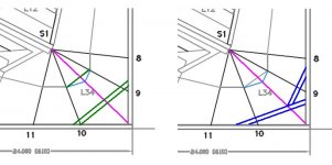
Now I will show the difference what it makes for corner bracings.
On the left the method how it is done by the 4 reference points method.
On the right how it is done by the 7 reference points method by 2 pieces instead of one.
In 'huge' corners (like in the big cab) I suggest 3 pieces...
The importance of those 'new' 3 reference points is this: The all point the the max (corner) and minimum path width that are not 'visible' with the method that is used around here...
Attachments
djim:
I like the way you think.... and some how, I think I owe you...
yes, my learning was definitely, 'the hard way....'
Not at all JBell... and thanks for my broken lips after the cold carnaval event over here
"stupid" flutes...(Oh and another more important thing I still on that challenge, improving that 'silly' concept of yours!)
Last edited:
And my second suggestion (before I fall in sleep). If you worry about point A, it almost follows the outline of the driver's cone. You can see it as a driver volume correction (in both ways). Tell me what you think...
Btw it was my intention to lift the driver panel parallel from its original position... sorry for my skills
The extra volume around corner one is now partly 'used' by the driver panel.
Btw it was my intention to lift the driver panel parallel from its original position... sorry for my skills
The extra volume around corner one is now partly 'used' by the driver panel.
Attachments
Last edited:
I am lost in the need for this "area" accuracy around the bends.
Previously I have seen the experts and good amateurs telling us that for low freqency reproduction that step changes in area make no difference to the sound that comes out.
I remember one designer saying that an LF horn would work just as well with cascaded parallel sections of increasing area.
They further went on to say that filling in the corners with rounded profile was a waste of effort and material.
DJM in his graphical method of minimising the "area" change is slowly approaching a curved "bend".
Is this really going to affect a speaker that has a maximum upper passband frequency of 60 to 120Hz?
Hi AndrewT,
Post #598: "Is this really going to affect a speaker that has a maximum upper passband frequency of 60 to 120Hz."
I doubt it, but both screamerusa and jbell have seen measurable differences in their respective tapped horns by using reflectors. So far nobody has reported controlled and repeatable measurements of the effects of reflectors in a tapped horn. So beyond screamerusa's and jbell's reports, we are just guessing.
I think they are most useful for freeing up space for wheels, handholds, and spots to the protect the input connectors. They can also be great to strengthen the box. Reflectors right around the throat area do make a difference in Hornresp, particularly when they affect the S1/S2 region.
One more note to the centerline discussion, soho54 has suggested that his corner method (which is what I'm using now) arrives at dimensions that produce Hornresp outputs that correspond to his measured results. I've tried a number of different ways, and there is just not enough difference to matter much. I do think it is worthwhile to enter a design into AkAbak prior to building, as most of the tapped horns that have multiple bends also end up having multiple tapers (flare rates), here AkAbak can give you a more correct simulation.
Regards,
- Home
- Loudspeakers
- Subwoofers
- Single sheet TH challenge