As far as tapped horns, the minimum impedance is usually quite close to the DC resistance, so is important when choosing an amp to drive the load.
The first low-impedance dip of traditional basshorns is usually very close to the DC resistance value too. The second dip is usually much higher. A 25% increase isn't uncommon. But, yeah, every basshorn I ever measured had impedance minimum in the passband that was very close to DC resistance. So I suppose I could have just slapped an ohmmeter across the leads but I always thought it was probably best to use that first dip as the Zmin value.
I also tried to explain how HornResp seems to be using some sort of steps in finding its lowest impedance point for its calculation and David explained to me in post#1379 it is limited by the graphic resolution of screen pixels.
This is what David says about the algorithm used to calculate:
Voltage Eg is automatically adjusted by Hornresp to maintain a constant 1 watt input, even though the load impedance changes with frequency.
The Hornresp model maintains power constant, not voltage. This makes impedance a non-issue with respect to drive voltage. The simulated drive voltage could be said to fluxuate, tracking the impedance curve.
We need to know Zmin when comparing measurements. To set the drive voltage for a reference power level we need to figure impedance.
Essentially, I take the speaker outdoors and use a swept sine to measure impedance. Then I examine the chart for Zmin, minimum impedance above cutoff. Next I calculate the drive voltage required to attain a specific reference power level. Then I set the (RMS AC) voltage drive to that reference value, e.g. 28.3v for 100 watts if Zmin is 8Ω. Then I position the microphone and run a sweep to get a response chart that shows SPL as a function of frequency.
Hi Wayne,
When you calculate the drive voltage required to attain a specific reference power level, do you simply use the magnitude of Zmin and consider it to be a pure resistance, or do you treat Zmin as a complex impedance having both resistive and reactive components? The voltage will be slightly different for the two cases.
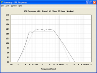
The attached screenprint generated using the default Hornresp record compares the true 1 watt / 1 metre response (black trace) against the response obtained by setting Eg to the voltage required to deliver 1 watt into the chosen Zmin value (gray trace). As you can see, there is a reasonable difference between the two. The only point at which the two traces exactly coincide is at the frequency of the minimum impedance within the nominated passband. For this particular example, the minimum impedance happens to be at the very top of the selected bandwidth (at around 800 hertz).
Kind regards,
David
Attachments
Last edited:
so, is there a winner? i wont read 140 pages but i might build the best single sheet box.
is there a link to the plans/ driver??
If you go back to post # 381, jbel writes:
“Yea, the dual lab smokes the ss15 below 40hz, ss15 smokes the dual lab 50hz on up. With that whole 'iron law' thing, you can have any 2, loud, low, small.”
The dual Lab 12 design uses less than a single sheet of plywood, and has far less distortion than the SS15 using a 3015LF.
Plans are here:
FREE SUB PLAN: Dual Lab12 (Front Loaded) by Welter Systems
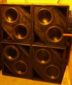
I have kept a pair of the 2x12" for smaller gigs, and have made a pair of tapped horns double the size of the 2x12" that I use for most shows.
The larger Keystone TH have more LF output of a pair of the 2x12" (and are lighter than a pair), and more upper output than the SS15, the best of both worlds, but take more than a sheet of plywood.
Art Welter
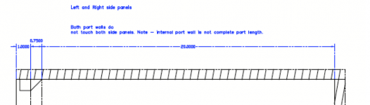
It is a basic BR cabinet, six sides, two triangular corner ports, all the details are in the link.sure would be nice to see some photos of the construction of a dual lab 12, ive built dozens of subwoofers over the years but cant quite make out how the build is supposed to go from the drawings i can find and photos of finished boxes?
The only thing unusual at all is the ports are fairly large and have a 45 degree angle on the outside and inside so the grill frame becomes part of the last 3/4".
That detail keeps the cabinet sounding basically the same at any power level below Xmax.
I used shells from old FLH cabinets to make my 2x12", the destruction details would have been interesting, but I did not photograph them.
The placement of the in/out connectors made putting a cabinet divider difficult, if I were building from scratch I'd add one.
The photo below shows the front of four cabinets with the grills removed.
You seem to be looking for 31 Hz response, the ports could be lengthened slightly, response would flatten out and drop a bit, at the expense of a little 50 Hz area output.
Art
Attachments
Last edited:
ok thanks i think i get it?
box is 21" deep, ports are 16.5 deep (longer is lower tuning) with 30 sq" area each?
a 3D sketch-up sure would be nice")
RAM Designs: T-line Box Design for True Bass 8" Subwoofer - YouTube
box is 21" deep, ports are 16.5 deep (longer is lower tuning) with 30 sq" area each?
a 3D sketch-up sure would be nice
RAM Designs: T-line Box Design for True Bass 8" Subwoofer - YouTube
Not quite, Seth H. Bass Box Pro sketch did not include the front baffle recess, you can see that in the thumbnail in the very first post, included below.box is 21" deep, ports are 16.5 deep (longer is lower tuning) with 30 sq" area each?
The interior depth is 20", interior height is 21 (22.5-1.5").
Reading through the two pages of posts should answer any other questions.
This is a very basic box, as long as you use big flared corner ports and keep the interior volume close to the same, it will perform fine.
There are now many drivers that cost less than the Lab 12 with similar TS parameters (and more Xmax) that would work well in this size box.
Art
Attachments
Last edited:
The reason for the difference is mostly due to one curve being generated by a constant voltage source and the other being driven with constant power. Remember that when we measure, we're dealing with amplifiers that are essentially constant voltage sources.
Hi Wayne,
Exactly - and because of this, the result is only going to be an approximation to the actual 1 watt / 1 metre performance - which is the point I was trying to make in my example
.Since the measured result is only going to be an approximation at best, why not just use the published rated impedance of the driver, rather than going to the trouble of finding a value of Zmin for the system? The difference between Re and the magnitude of Zmin will not be much. Using Re rather than Zmin would mean that it is no longer necessary to identify the passband in order to establish a value for Zmin.
Kind regards,
David
Exactly - and because of this, the result is only going to be an approximation to the actual 1 watt / 1 metre performance - which is the point I was trying to make in my example
Yes, that's the same point I was making. So we're square on that.
Since the measured result is only going to be an approximation at best, why not just use the published rated impedance of the driver, rather than going to the trouble of finding a value of Zmin for the system? The difference between Re and the magnitude of Zmin will not be much. Using Re rather than Zmin would mean that it is no longer necessary to identify the passband in order to establish a value for Zmin.
Not sure I understand what you are saying. The measured result is an approximation? Actually, the measured result is the real deal. The simulation is what is the approximation. I mean, I think the model is very good, but it is a model, after all.
But now that I consider your meaning a little more, I don't think your statement was about comparing the measurement to the model, I think you were talking about what single-point impedance value to chose when calculating drive voltage for measurements. If so, then, yes, that's the problem. That is the dilemma.
If we wish to make SPL measurements of loudspeakers at consistent power levels, then we must understand their impedances to calculate their drive voltage requirements.
I agree with you that Re is perfectly acceptable. Zmin or Re. Both are pretty close to the same, and either one is what I would use. I have been inclined to use the value of Zmin in the passband, usually the first impedance minimum after the first peak. But it is, in fact, usually almost exactly the same value as DC resistance. So I'm perfectly satisfied with using either one.
To further the thought experiment, for others that might consider this dilemma:
We can't just say constant power must be used, because this side-steps reality. The amplifiers used to drive these speakers are essentially constant-voltage sources. You can argue whether or not they should be constant-current sources, but that's another matter. The fact is, they are constant voltage sources.
So that being said, if we want to compare measurements between speakers, if we want to use uniform power values as reference levels, e.g. 1W, 100W, etc, then we have to understand impedance. As has been rightly shown, impedance fluxuates across the passband, both in amplitude and in phase (resistance/reactance).
So what do we do? Do we measure and use Zavg? Do we use Re or Zmin? Or do we use the manufacturer's advertised impedance and call it good?
I don't think using advertised impedance is appropriate, since it can be pretty far off. Most times, manufacturers round to the nearest multiple of 4, 8 or 16 ohms. Seems pretty common to find speakers that are advertised as 8 ohm speakers but are actually 6 ohms, for example. One can usually find accurate values in the datasheets, and so I would be comfortable using the manufacturers specs in most cases, just not the advertised (4/8/16Ω) value. But really, even if I trust spec sheets, measurements are there to verify, so I think it only makes sense to run an impedance sweep and use the values found.
So throwing out the advertised impedance, that leaves me with two choices, Zavg or Zmin. Honestly, in my opinion, both Zavg and Zmin are just fine. When you run the numbers, you find a worse case variance of about 1dB between Zavg and Zmin. It's usually only about 0.25dB to 0.5dB. But Zavg is not obvious and requires some calculation, whereas Zmin is dead simple and completely obvious. That tends to lean my decision towards Zmin.
Zavg is a little bit higher than Zmin due to the influence of the impedance peaks. And to find it, you have to define an upper edge of the passband, since this will determine the area under the curve. But using Zmin is not subject to interpretation. It's repeatable and easy for anyone to find in an instant. So since using Zmin gives results that are less than a decibel off the Zavg values, and since it tends towards the conservative where SPL is concerned, I have always found it to be the most attractive method for setting drive voltage.
Hi Wayne,
Sorry for the ambiguity.
I was just making the observation that the measured result gives the true 1 watt / 1 metre response at a single frequency only, not across the entire bandwidth.
As far as Hornresp is concerned, the attraction of using Re rather than Zmin is that it no longer becomes necessary to identify an appropriate passband for a particular speaker system, or to find the value of Zmin within that passband.
This makes it much easier to provide the sensitivity tool requested by Djim.
Kind regards,
David
Not sure I understand what you are saying. The measured result is an approximation? Actually, the measured result is the real deal.
Sorry for the ambiguity
.I was just making the observation that the measured result gives the true 1 watt / 1 metre response at a single frequency only, not across the entire bandwidth.
I agree with you that Re is perfectly acceptable. Zmin or Re. Both are pretty close to the same, and either one is what I would use. I have been inclined to use the value of Zmin in the passband, usually the first impedance minimum after the first peak. But it is, in fact, usually almost exactly the same value as DC resistance. So I'm perfectly satisfied with using either one.
As far as Hornresp is concerned, the attraction of using Re rather than Zmin is that it no longer becomes necessary to identify an appropriate passband for a particular speaker system, or to find the value of Zmin within that passband.
This makes it much easier to provide the sensitivity tool requested by Djim.
Kind regards,
David
As far as Hornresp is concerned, the attraction of using Re rather than Zmin is that it no longer becomes necessary to identify an appropriate passband for a particular speaker system, or to find the value of Zmin within that passband.
This makes it much easier to provide the sensitivity tool requested by Djim.
I think Re is fine, since it is almost always very close to Zmin.
On the other hand, my definition of Zmin being the minimum impedance above cutoff is equally determinite, and has the advantage of being something that all agree is in the passband. You'll find people that complain about DC resistance not being "accurate", since the speaker never has DC applied.
You do not have to define the passband to find Zmin. You only have to know one side of the passband - lower cutoff - which can be simplified to be the 1/4λ frequency. This is a useful simplification since Zmin will always be above that point. The other side - the mass-rolloff point - is not important for this determination. Horns are often used above this but impedance is rising, at least when driven with a speaker having a voice coil. So you can use an arbitrarily high frequency for the upper bounds. Use 20kHz if you want. The point is to find the minimum impedance above lower cutoff.
I think we're definitely splitting hairs here though. I'm sure you could use either Re or Zmin and get the same results to several significant digits.
How do we carry out a sensitivity measurement of a real speaker?
Do we supply a band limited pink noise, or white noise, or some other defined noise, to a speaker and measure the voltage and the current at the speaker terminals and the SPL at the test distance?
I asked a while back and now I see Wayne asking the same question...............if we want to compare measurements between speakers, if we want to use uniform power values as reference levels, e.g. 1W, 100W, etc, then we have to understand impedance. As has been rightly shown, impedance fluxuates across the passband, both in amplitude and in phase (resistance/reactance).
So what do we do? Do we measure and use Zavg?
How do we measure the power sensitivity of an actual speaker?
- Home
- Loudspeakers
- Subwoofers
- Single sheet TH challenge