Martin, thanks for posting the extended SS15 with 3,06m pathlength elsewhere  Maybe you could post it under its own thread (and/or here ;-) as it could be the answer (at least it looks promising) for some people before it gets lost between all suggestions...
Maybe you could post it under its own thread (and/or here ;-) as it could be the answer (at least it looks promising) for some people before it gets lost between all suggestions...I would like to add something. Since we can't argue their thermal compression figures since they lack any further information it seems dynamic compression figures are not mentioned either. What I do know is that in tests other PD’s were not better scoring in (lower) pwr compr figures then 'Italian' drivers so it looks like 2,4dB to 3dB total pwr compr. at AES cont. power rating is very likely.In the UK the Eminence 3015lf is currently retailing at about £137
As an alternative I think that the Precision Devices 15" Neo. PDN15BR40 looks to be a good match. It retails at approx £158, is rated at 700W AES, & has a X max of 10.5mm. Maybe more importantly it has a 4" voice coil compared with the Eminence 3".
As usual no figures for thermal compression.
The only quoted thermal compression figures I can find on Precision Devices site are for the PD1850 18" (1.6db at 800W) and the PD1851 (1.7db at 1000W)
The low thermal compression of the PD 18" drivers is no doubt helped by the 5" voice coils.
Last edited:
Djim thanks for pointing out that the PD thermal compression figures do not give the complete picture.
The PDN15BR40 driver on paper seems to have low efficiency at a quoted 96dB/W but when simmed in a TH like the SS15 seems to have the same 'magic' as the Eminence 3015LF in as much as the efficiency of the sim at 1 watt is maybe 2 db more than most drivers. This combined with its increased power handling suggests to me that it is a good substitute driver for the SS15.
As for the 18" extended SS15 layout http://www.diyaudio.com/forums/subw...30-ft30-pa-th-awesomeness-22.html#post2548377 it was posted as a direct response to Crescendos request for a more compact design. I did not really want to dilute this thread with more variations on a theme.
The SS15 style layout is difficult to fold consistently. I am developing this idea still further with all the amassed knowledge that is available on the forum. Albeit at a slow pace as I am very busy at the moment with work.
It's a case of lots of time and no money - or money and no time!
Eventually my target is to build a pair of TH cabs for myself.
I have a mate who has built 8 off PD1850 FLH cabs who can get PD drivers at a good price and has good joinery skills, so eventually I should get around to producing my own killer project to document and share
Martin, the 96dB sensitivity for the PDN15BR40 shows it is build for low frequency just like the classic RCF L15P200AK and others. These drivers may look less sensitive but in fact if you look to the > 80Hz bandpass they should have better sensitivity then most other drivers. Sensitivity data as part of Thiele-Small are often measured by AES standard bandpass from 100 to 500Hz. That is why these specialized extended LF drivers look less efficient when it comes to sensitivity. For years this has been discussed in the AES organisation but still there is no specialised extended LF bandpass (40-100Hz) measurement standard.
Anyway, I’ll try to get some pwr compr. info about this PD driver so I can do some more accurate modelling with the SS15. The only worry I have is its relative low Bl force. In the SS15 this driver could face some physical difficulties especially at high power but I will check that out.
Your 18”extended SS15 seems to work for 15” drivers also. +5dB at 40Hz and just -1dB overall compared to Jbell’s SS15. In stacks your extended will even more blossom since its 1/3WL is at 38Hz (Jbell’s SS15 1/3WL is > 47Hz). I guess you didn’t choose 38Hz consciously but this is a very good choice since it stays above the Fs of many drivers.
8 PD1850’s in FLH’s, sounds like a Turbo fan to me . Time or no time, you seem to manage to pull out some interesting designs in between all that work.
but still there is no specialised extended LF bandpass (40-100Hz) measurement standard. Anyway, I’ll try to get some pwr compr. info about this PD driver so I can do some more accurate modelling with the SS15. The only worry I have is its relative low Bl force. In the SS15 this driver could face some physical difficulties especially at high power but I will check that out.
Your 18”extended SS15 seems to work for 15” drivers also. +5dB at 40Hz and just -1dB overall compared to Jbell’s SS15. In stacks your extended will even more blossom since its 1/3WL is at 38Hz (Jbell’s SS15 1/3WL is > 47Hz). I guess you didn’t choose 38Hz consciously but this is a very good choice since it stays above the Fs of many drivers.
8 PD1850’s in FLH’s, sounds like a Turbo fan to me
. Time or no time, you seem to manage to pull out some interesting designs in between all that work.Attachments
Last edited:
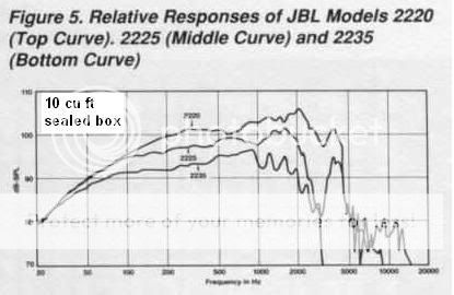
Note that at LF all the drivers are basically the same efficiency, even though there is 9dB difference mid-band (200hz~400hz). The least efficient driver ultimately has the greatest x-max, and thus the greatest bass output. No-=% is only for the octave between EBP and the mass corner.
Note that the least efficient driver has the most SPL in the 70hz region, and that the most efficient is going to need at least 3dB more power to have the same output (graphs at 80V RMS drive level).
Last edited:
Djk, I'm not sure what you are trying to say. In your example you are using drivers of the same brand that were using the same measuring method for measuring sensitivity. Also your example is from different 'type' of drivers and just one could be called an extended LF driver (I know, not a real definition but some European companies use it for their drivers with a dedicated LF task - high Xmax drivers).
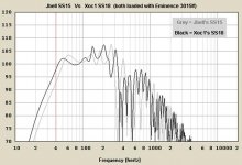
In case of Xoc's example both drivers 3015lf and PDN15BR40 have similar Xmax, similar BL and similar mass but different 1w/1m sensitivity data. When you both load them in a SS15 both will have similar 1w/1m sensitivity.
1.) Isn’t the difference in sensitivity because Eminence uses Quote: “the average output across the usable frequency when applying 1W/1M into the nominal impedance.” While Precision Devices uses a standard AES protocol of 50Hz-500Hz, 1W/1m for measuring sensitivity?
2.) Doesn't that mean if you look to the <80Hz area from so called extended LF drivers you can compare the sensitivity better in the sub frequencies?
Last edited:
The cone area determines the LF output.
This applies whether the driver is very efficient or off ordinary efficiency or of low efficiency.
The efficiency further up the frequency range is determined by the parameters that control efficiency, only one of which is cone area.
Djk seems to be pointing out that improvements in the upper range efficiency are influenced by parameters that reduce LF output. I think he is suggesting that the parameters that give the required LF output, i.e. cone area and optimised parameters that give medium upper range efficiency tend to allow for a better low end performance than if all parameters are optimised for highest efficiency.
Thank you for taking the time to explain - I appreciate it and now understand what you were saying
Is there a tool/instrument/device to measure the xmax of a driver while loaded in an enclosure?
Is there a tool/instrument/device to measure the xmax of a driver while loaded in an enclosure?
Crescendo, I have to apologise for my fuzzy explanation. Besides the language barrier and between all kinds of work, it still difficult to explain in a few words but I’ll try.When people (including myself) talk about power compression it is not always clear what part of the pwr comp. they are referring too:
1.) Thermal power compression: which is the result of electrical values. More power input means more temp rise (which leads to increase of resistance and such)
2.) Dynamic power compression: which is the result of physical values. The higher the excursion becomes the higher the dynamic power compression values become.
When a driver is forced to go below its own Fs excursion will (dramatically) rise as frequency drops. When the driver Fs is higher than the Fs of the system, the Xmax will be reached with less power. But the confusion started when I stated
Instead I should have stated: If your TH's 1/3WL is much below the Fs of the loudspeaker in free space, the thermal pwr comp levels will be lower as max excursion will be reached with much less power. The dynamic compression figures will be higher as max excursion will be reached with less power.
Now back to your question;
No, I expect the L15P200AK with its lower Fs will have less thermal power compression then the 3015lf at the same power in a SS15. Besides power compression I do have my doubts about the 3015lf Xmax data as given by Eminence. Nobody seems to know how Eminence today calculates their Xmax any longer.What I do know is what people show me in their measurements and these give me reasons to believe that the total power compression figures are higher then 3dB at Xmax.
Therefore I would like to see a side by side comparison of an SS15 loaded with 3015lf and L15P200AK.
Hopefully this makes more sense and is lessconfusing
Also, I may be willing to purchase 1 or 2 L15P200AK drivers to test against my 3015LF drivers. What guidelines would deem this battle legit?
I'm thinking, same: enclosure, testing equipment, day, distance, power level
And test different: power levels, distances..
If we can (collectively) agree on these things, I'll heavily consider buying the driver(s).
I see that most of the time, a wide open outside space is preferred. But, is it mandatory? Maybe if the position of the enclosure outside and the structures around it aren't TOO close and are constant, valid test may be made.
Thoughts?
Thank you for taking the time to explain - I appreciate it and now understand what you were saying
Is there a tool/instrument/device to measure the xmax of a driver while loaded in an enclosure?
Davy measured displacement in a horn-loaded cabinet using a radar a while back.
It is a lot easier with a tapped horn - you can usually see or touch the cone.
Crescendo, there is no commercial tool for measuring Xmax. I have seen different methods from high speed camera’s or lasers to a simple paperclip with a ruler so its up to your imagination and your budget. Just keep in mind the more complicated you make a measurement the more can go wrong.
If you want to compare the L15P200AK with the 3015lf you need power. In sensitivity test (1w/1m) they probably measure the same. At full continue sine wave power for the 3015lf (450Watt IEC standard) you can expect to see/hear a difference in favour of the RCF. The cause is the expected higher power compression of the 3015lf at this point. Also it wouldn’t surprise me if you will see a bigger difference below 60Hz then in the higher frequencies. It is this part of the bandpass I’m particularly interested in.
The RCF also has quiet some headroom left since that driver should be able to handle 750Watts continue sine wave power. For music power you will need an amp of 1500 Watts (peak) to get the full power out of the L15P200AK. But as usual in both cases use your ears to hear if the sound doesn’t get distorted.
The reason a open space (2Pi) is preferred is to make sure no external factors like reflection from objects/buildings will take place. Especially in room measurements can have dramatic effects on your measurement. For instance 1 meter change in position indoors can give completely different results. Therefore measuring outside and if possible as far as possible from any building or objects is preferable. Sand walls/bluffs have less influence then structures. Sand has the ability to absorb sound waves.
Few notes:
1.) Good measurements start with good planning and preparation.
2.) Both drivers have a different resistance (Re) which means you need to calibrate them independently to get 1w/1m.
3.) If you don’t have access to a True RMS meter specialised for audio measurements you can’t measure music or complex audio signals. With standard multimeters (true RMS or not) you can only measure sine-waves. True RMS is not really necessary although it should give you more accurate results (the difference isn’t as big as many people suggest here on the forum).
4.) Use a quality amp for high power measurements to make sure you can ‘feed’ the drivers with clean power.
5.) Make sure your power supply cabling is able to handle the power the amplifier needs. Also make sure the loudspeaker cable is short as possible and able to handle the heavy loads.
6.) Always write down (logbook) every step, every change in your measurements.
My QSC RMX2450 can supply 1300W rms FTC/1500W rms EIC @ 8 ohms/0.1% THD (bridged). Would that be acceptable?
First of all, my plan is to test outdoors. The further other objects are, the better. But, how far must they be (at least) to deem the experiment valid?
The steps above sound good and do-able to me. I do not own an RMS meter though. Not sure what type is recommended and/or if they are pricey either. I would definitely be interested in investing in one if it won't break the piggy bank.
Anyone get wholesale prices on RCF goods?
There is no general rule for distance of objects/buildings. It also depends on how big they are and the direction of the wind. Just try to get as far away as possible but if you post your measurements make a small map of the surroundings so everybody is able to see the influences.
You don’t actually need a True RMS meter if you measure with continue sine wave signals around 50Hz. If you calibrate power (by measuring AC Voltage) start at point where the impedance is the lowest in the HornResp prediction. In case of the SS15 that is around 45Hz (that is also close enough to your multimeter calibration point of 50Hz).
Any relative cheap multimeter will do. However, the more digits behind the dot the more accurate is suppose to be. That’s why I prefer to use a multimeter with at least 3 digits behind the dot so you can calibrate to 2,830 AC/Volts. If you use a meter with only 2 digits behind the dot you can end with 2,839V or 2,821V in a worst scenario.
Most people here on this forum set their amp to 2,83Volt for their SS15 but that is actually not correct. That’s why they measure higher 1W/1m SPL figures as predicted by HornResp. If you want to compare with other members here on DIY you should use this ‘incorrect’ method.
If you want more correct measurements you need to measure first the Re of the driver + the connected loudspeaker cable. It will be around 5,4Ohm (1watt = 2,3238 Volts in this case). For a handy online calculator you can use this link.
This method only works for continues/frequency stable sine waves. Complex signals or signals of different form can only be measured with specialised equipment.
You seem to use the old specs of the driver that show better Thiele-Small parameters.
The Kappa Pro-15LF-2 at 53 volt has a theoretical HornResp excursion of 10,5mm. The reality is this drivers suffers from at least 3dB pwr/dyn compression at Xmax. This means you will need twice the power to reach Xmax in reality.
Xmax theoretical = 40V at 6,12Ohm = 265Watt
Xmax theoretical -3dB pwr/dyn compression = 530Watt
Like I said at LEAST 3dB so powering this driver to its 600 watts continues power rating is absolutely NO problem!
That's why I said people are way to much concentrating on theoretical Xmax while they don't seem (or want?) to understand the impact of power/dynamic compression. Although I never work with Eminence the 3dB seems to be the (lowest) value I get from other users.
As far as I know only RCF and 18Sound include pwr compression data with their drivers.
If I'm getting this right, though it will take more power to get the Kappa Pro 15LF-2 to reach xmax due to compression, it will still only put out the modeled SPL at its xmax (125dB @ 100Hz @ 6.7mm xmax, for example) -- if I'm understanding this correctly from our other thread:
Excursion is directly coupled to SPL and power not. So less excursion (because of pwr comp) results in less SPL.
If this is correct, the Kappa Pro 15LF-2 at xmax is 3dB quieter @ 100Hz than the 3015LF at xmax (128dB @ 100Hz @ xmax)
Since both drivers are susceptible to either types of compression, the Pro 15LF-2 might make it closer to xmax (in turn, closer to the modeled SPL) a little easier than the 3015LF since it's further from its thermal limits than the 3015LF at their modeled xmax -- the Pro 15LF-2 is still quieter at xmax, however.
Am I narrowing in on this correctly?
In my quote about the 3015lf I was using info from others. I don't know the exact numbers for Eminence drivers. All I know is that Eminence doesn't supply enough information and what they supply is not confirming AES standards. But it looks like you got it right in theory.If I'm getting this right, though it will take more power to get the Kappa Pro 15LF-2 to reach xmax due to compression, it will still only put out the modeled SPL at its xmax (125dB @ 100Hz @ 6.7mm xmax, for example) -- if I'm understanding this correctly from our other thread:
If this is correct, the Kappa Pro 15LF-2 at xmax is 3dB quieter @ 100Hz than the 3015LF at xmax (128dB @ 100Hz @ xmax)
Since both drivers are susceptible to either types of compression, the Pro 15LF-2 might make it closer to xmax (in turn, closer to the modeled SPL) a little easier than the 3015LF since it's further from its thermal limits than the 3015LF at their modeled xmax -- the Pro 15LF-2 is still quieter at xmax, however.
Am I narrowing in on this correctly?
The thermal capabilities of a driver are set out by the AES power ratings. Therefore if you need to reach Xmax (BL70%) or even Xvar (BL50%) in reality you need to check the power ratings of the driver if the voice coil is capable of handling the power. That's why I stated that people shouldn't focus so much on Xmax and instead focus on the power ratings. And again, if the Fb of the system is below the Fs of the driver it will be different.
Normally when they design a quality PA driver they search for a balance between power ratings and excursion. In other words, a well designed PA driver should reach its Xmax around its AES continue power rating and its Xvar around its max power (and still have enough crest factor to deal with power peaks). But the reality is that not every brand use this principle of balancing their drivers.
Last edited:
Cheap 80 Euro alternative for Eminence 3015lf
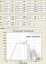
For the European DIY builders on a very tight budget there is a cheap alternative driver for the SS15, the DAP AB-15 that you can find for about 80 Euro's.
Although factory specs suggest it is rated as 400W continue and 800W max, I wouldn't go beyond 500Watts that much. Still, for the price for one 3015lf you can have 2 Dap's.
Attachments
As requested, here's links to the plans. (is there a moderator way to add this info the post1???)
http://www.diyaudio.com/forums/atta...th-challenge-singlesheet_2_2010_aug18_dwg.pdf
http://www.diyaudio.com/forums/atta...challenge-2011_mar12_ss15_profile_revised.pdf
These come from post 74 and post 622. Kappa pro 15lf2 works in place of the (now) more expensive 3015lf, as do several other drivers.
Thanks to all who contributed.
Fiction or truth?
Jbell, a while ago you asked why the LF output looks different from predictions, especially below 1/3WL. I’m working on a possible answer that I want to show.
Think of flutes, remember? 1/6th extension outside the cab, (1/3 WL) 50Hz – 1/6th = 50 – 8,3 = 41,7Hz (ring any Jbells yet, try the harmonic tests with same Voltage from 40 to 44Hz by 1/2Hz steps)
Now the big question, what if the main system works as a Tapped Horn but the driver also sees an Offset Horn in the same construction. Now let’s see what HornResp says:
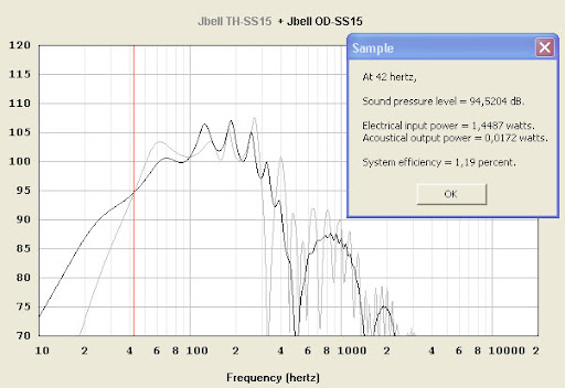
You can clearly see where the two designs cross each other 41,7Hz (coincidence?). You can also see the LF extension below this point. Also look carefully to the +60Hz knee in the response of the offset horn. Now think how these two graphs can influence and integrate with each other (and what would the possible outcome be if you add both).
Compare those findings, to what you have measured with your Smaart and see if you find any resemblances (Ps did you make measurements without Low-cuts yet)?
Jbell, a while ago you asked why the LF output looks different from predictions, especially below 1/3WL. I’m working on a possible answer that I want to show.
Think of flutes, remember? 1/6th extension outside the cab, (1/3 WL) 50Hz – 1/6th = 50 – 8,3 = 41,7Hz (ring any Jbells yet, try the harmonic tests with same Voltage from 40 to 44Hz by 1/2Hz steps)
Now the big question, what if the main system works as a Tapped Horn but the driver also sees an Offset Horn in the same construction. Now let’s see what HornResp says:
You can clearly see where the two designs cross each other 41,7Hz (coincidence?). You can also see the LF extension below this point. Also look carefully to the +60Hz knee in the response of the offset horn. Now think how these two graphs can influence and integrate with each other (and what would the possible outcome be if you add both).
Compare those findings, to what you have measured with your Smaart and see if you find any resemblances (Ps did you make measurements without Low-cuts yet)?
Hmmm.... have to think on that a bit. I do know I've asked if I need to take 'horn bubble' into account, because every TH plays just a bit lower than hornresp says, and I've been told it's already accounted for... But yes flute and 1/6th -- got it.
I will tell you, because I've done 1hz sine wave tests... 42hz is the edge of the cliff. It's freefall from there on down.
For whatever reason... I have only done tests with my high pass on, even the current 32hz 24db/oct high pass. I guess I just have this feeling in the back of my mind, that I'll disable the high pass, and then a surprise will happen later... (oops, sorry dad... cooked your sub... but it was fun while it lasted !!)
I'd rather keep the high pass, and the password protection on the crown... just for my peace of mind.
Last edited:
- Home
- Loudspeakers
- Subwoofers
- Single sheet TH challenge