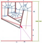
Andy, grey lines "old" situation, red lines my suggestion. However, it's not accurate yet for a final drawing. The total volume of S1, S2 until the first bend wont change that much and that's more important then a correct visualisation. I expect changes (positive) in the upper part of the bandpass.OK then make S1 and S2 smaller? Why did you open up the S1 area again? Andy
Attachments
Last edited:
Hi Djim,
I'll attach a revised drawing of the original SS15 horn path, and a .xls file with the data point (had to rename the .xls file as .txt to get it uploaded, to use: change the extension back to .xls).
Regards,
I'll attach a revised drawing of the original SS15 horn path, and a .xls file with the data point (had to rename the .xls file as .txt to get it uploaded, to use: change the extension back to .xls).
Regards,
Attachments
hi oliver i like the mod in this postHi Djim,
I'll attach a revised drawing of the original SS15 horn path, and a .xls file with the data point (had to rename the .xls file as .txt to get it uploaded, to use: change the extension back to .xls).
Regards,
not only the path is longer but it also stiffens the back pannel..
that and 2 deflectors in the last 2 corners ,you do not need bracings(except the flappy ends) imo.
regards erik
Last edited:
A few questions and assumptions of mine that might be misguided:
The most limiting factor is the mouth size? Which is restricted by
the total internal volume available to expand toward that size.
Maximum internal volume for a given amount of side area is a cube?
Though this assumption does not account for area used by internal
baffles and bracing, maybe a cube makes this worse?
What of the floor? Can it be a "side", would that be a legit cheat?
I've never built any tapped horn, but did build a Karlson K15 once.
Thats definitely tapped, hybrid of too many things to say for sure
why it behaves as it does, and almost exactly 1 sheet. Effective,
but not sure how it compares against a horn of that same 4x8??
Jbell post 12
BTW -- leaving out the bottom panel and saying "just sit it on the floor" is cheating.....
Hi 4pyros,
Responding again to your question in Post #583: "Can you get it to bend at S3?" I changed the flare from S2 to S3 to an even 3degrees, and then started into the same angle as your driver mounting board, that will do it, no major change in Hornresp:
Regards,
Responding again to your question in Post #583: "Can you get it to bend at S3?" I changed the flare from S2 to S3 to an even 3degrees, and then started into the same angle as your driver mounting board, that will do it, no major change in Hornresp:
Regards,
Attachments
Hi 4pyros,
Post #623: "...does not look like you moved the path lenght out to the mid point of the long lines..."
Because soho54's method does not use the long lines in the corners, and he has done a lot of testing comparing simulations to actual tapped horns, so I'm sticking with his method for the overall corner length.
Regards,
Djim
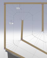
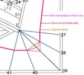
I added 3 extra lines to the corner sketch, making 7 in total - the extra line that you want to add at the beginning of the bend seems wrong to me as this line is before the corner actually starts.
I should explain that when I sketch in the lines to measure the corner, that the first line is perpendicular to the previous centre line, before this point in my opinion the expansion is linear.
The last line through the corner is perpendicular to the outside wall as this is the shortest distance.
I have attached some screengrabs of what I have done so far for you to appraise. Is this what you are trying to acheive?
I am busy at the moment, and will continue to be for the next 3 months so it may take some time to get back to you.
I have based my dimensions on the PDF files in posts 74 & 82 by TB46
Can anyone confirm that these are the most accurate drawings of the SS15 as it stands?
As for modifying the ss15 it is very tricky to improve on what JBell has done with 1 sheet of timber.
You could shorten the 8" mid panel a little to get a more linear expansion (at the expense of the path length)
You could lengthen the baffle to make the last corner more smooth.
but that makes it a ss & a bit more 15
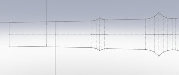
I found JBells explanation of the shape that he was trying to acheive very interesting. The expansion of the horn then emulates a parabolic shape.
I am trying to develop that idea by sketching the unfolded path of a TH with an expansion based on a segment of an elipse
Regards
Martin
I added 3 extra lines to the corner sketch, making 7 in total - the extra line that you want to add at the beginning of the bend seems wrong to me as this line is before the corner actually starts.
I should explain that when I sketch in the lines to measure the corner, that the first line is perpendicular to the previous centre line, before this point in my opinion the expansion is linear.
The last line through the corner is perpendicular to the outside wall as this is the shortest distance.
I have attached some screengrabs of what I have done so far for you to appraise. Is this what you are trying to acheive?
I am busy at the moment, and will continue to be for the next 3 months
so it may take some time to get back to you.I have based my dimensions on the PDF files in posts 74 & 82 by TB46
Can anyone confirm that these are the most accurate drawings of the SS15 as it stands?
As for modifying the ss15 it is very tricky to improve on what JBell has done with 1 sheet of timber.
You could shorten the 8" mid panel a little to get a more linear expansion (at the expense of the path length)
You could lengthen the baffle to make the last corner more smooth.
but that makes it a ss & a bit more 15
I found JBells explanation of the shape that he was trying to acheive very interesting. The expansion of the horn then emulates a parabolic shape.
I am trying to develop that idea by sketching the unfolded path of a TH with an expansion based on a segment of an elipse
Regards
Martin
Attachments
Thanks Martin for dropping by and I didn’t post you since I saw your absence around here, the man must be busy...
I do have a comment on the middle path route which you can see in my next post as an answer to Oliver his post. Yes! The idea of 7 reference points you are showing is exactly what I am after. I know my graphics are bad because I don’t have the right progs or skills so I only can use my bad eyes and unstable hand and use straight line as guidance (and most time I work with old fashion pen & paper). I use the same dimension from post 82 since it’s in metric numbers.
I know it’s tricky to change this SS15 concept but maybe there are small possibilities that can improve here and there a dB or something. Also I think there are possibilities with less known factors. But indeed it is very difficult to stay within the one-sheet-challenge. Sometimes experience gives more opportunities then just predictions simply because not all parameters are represented in HornResp. To name a few:
1.) Dropping of BL force in conjunction with excursion
2.) Absorption trough panels
3.) Air mass changes along the path (especially around ‘non gentle’ bends, I am looking in other areas to find more solid info on this matter)
4.) Imperfections of data (still looking for accurate measurements of 3015LF parameters)
Jbells goal of his parabolic was indeed very interesting to see lined up to the ‘roll-out’ from Oliver. Like I said before I was following your post with great interest since the horizontal representations or roll-outs do show more information that the visual of the cab. That’s why I need accurate roll-outs and along a (metric) scale. Anyway, thanks for responding and don't stare to much on those reports. Especial in the next three months when weather is changing
Last edited:
Hi Xoc1,
The pdf files in Post #74 & 82 are still the ones I work of, I used them as a base for Post #622.
There is some room for cleaning up the SS15 drawings, e.g.: getting the corners tight, and getting the dimensions of the wood pieces after cutting. I just couldn't see any reason for doing so, there has to be a little diy left for the individual builders. Same holds for improving the output, I think that within this form factor this is about all you can get out of the 3015LF. I still would like to see somebody measuring what happens when you set S1 to zero, and slant a board up from there to S2. According to Hornresp that would be an improvement. Jbell's explanation for how he arrived at the shape is interesting, one might be able to redesign the path to fit even better, but would it make a difference?
I really enjoy your drawings, very nice work. Looking forward to seeing what you'll do with this one.
Regards,
Oliver; Sorry I must be lost somewhare. Does your program automatically put the purple line in? I was not looking for a new S3 locashoin just a bend at the orginal S3 locashoin. Like in the one for Jims box. AndyResponding again to your question in Post #583: "Can you get it to bend at S3?" I changed the flare from S2 to S3 to an even 3degrees, and then started into the same angle as your driver mounting board, that will do it, no major change in Hornresp:
Oliver, many, many thanks .
.
For the middle path in corners I show you a drawing how I prevent 90 degree pathways (sound waves can bounce in 90 degrees only on hard surfaces). Btw, I use 2 x pi in bends for setting out the middle path...
And if it is not to much to ask for you and Martin, could you make a scale above the roll-outs with metric numbers every 10 cm (and tiny stripes for each cm, see picture). I don't like to ask you Oliver as I know it is time consuming but your excel sheet is in inches only. When I tried to change it I messed it up
As you can see your PDF files (in 100% scale) don’t line up with metric scale above it. For me that isn’t big problem as long you provide a metric scale aligned with the path. That way I can input your PDF’s in Photoshop en re-scale them to 'real' centimetres, perfect for prints and other metric graphs.
Anyways, it is great stuff you guys are producing!
. For the middle path in corners I show you a drawing how I prevent 90 degree pathways (sound waves can bounce in 90 degrees only on hard surfaces). Btw, I use 2 x pi in bends for setting out the middle path...
And if it is not to much to ask for you and Martin, could you make a scale above the roll-outs with metric numbers every 10 cm (and tiny stripes for each cm, see picture). I don't like to ask you Oliver as I know it is time consuming but your excel sheet is in inches only. When I tried to change it I messed it up
As you can see your PDF files (in 100% scale) don’t line up with metric scale above it. For me that isn’t big problem as long you provide a metric scale aligned with the path. That way I can input your PDF’s in Photoshop en re-scale them to 'real' centimetres, perfect for prints and other metric graphs.
Anyways, it is great stuff you guys are producing!
Attachments
Last edited:
Jbell post 12
Quote:
BTW -- leaving out the bottom panel and saying "just sit it on the floor" is cheating.....
I might be interested in cheating then... Who's with me?

Sure it helps, now I can show JBell in detail where his SS15 can be improved.
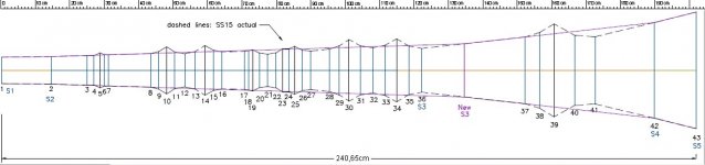
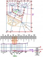
The air resistance point is situated between points 40 and 41. Here the path of the horn is squeezed together. This can be translated to the 78Hz area. I also coloured the whole area where the real cab is less in volume compared to the predicted model to make it more visual.
JBell measurement...Runrod1948 measurement
40hz 98.5.............40hz 101db
45hz 100.5...........45hz 104db
50hz 102..............50hz 108db
55hz 103.5...........55hz 109db
60hz 105..............60hz 111db
65hz 105..............65hz 111db
70hz 105..............70hz 112db
75hz 104.5...........75hz 112db
80hz 104.2...........80hz 110db
85hz 104..............85hz 112db
90hz 104..............90hz 113db
95hz 104..............95hz 112db
100hz 104.5..........100hz 113db
105hz 105............105hz 112db
110hz 105............110hz 112db
115hz 105.5..........115hz 113db
120hz 106.5..........120hz 113db
So please can anyone tell me; bad theory and another coincidence or correct theory and exact numbers showed by a lovely model of horizontal representation?
.The air resistance point is situated between points 40 and 41. Here the path of the horn is squeezed together. This can be translated to the 78Hz area. I also coloured the whole area where the real cab is less in volume compared to the predicted model to make it more visual.
JBell measurement...Runrod1948 measurement
40hz 98.5.............40hz 101db
45hz 100.5...........45hz 104db
50hz 102..............50hz 108db
55hz 103.5...........55hz 109db
60hz 105..............60hz 111db
65hz 105..............65hz 111db
70hz 105..............70hz 112db
75hz 104.5...........75hz 112db
80hz 104.2...........80hz 110db
85hz 104..............85hz 112db
90hz 104..............90hz 113db
95hz 104..............95hz 112db
100hz 104.5..........100hz 113db
105hz 105............105hz 112db
110hz 105............110hz 112db
115hz 105.5..........115hz 113db
120hz 106.5..........120hz 113db
So please can anyone tell me; bad theory and another coincidence or correct theory and exact numbers showed by a lovely model of horizontal representation?
Attachments
Last edited:
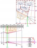
Another air resistance point you can find around point 21. Here is the narrowing also more then 1/6 of the path. It's centre frequency is 186Hz. The narrowing starts around 177Hz and ends around 195Hz.
I'm not sure what HornResp produces around this freq since I have seen several predictions (which one is closest?). If predictions already predict a notch around this frequency, the reality will be a more deep and wider notch then predicted. If you want to use the SS15 bandpass around this frequency, you can correct this point.
I'm not sure what HornResp produces around this freq since I have seen several predictions (which one is closest?). If predictions already predict a notch around this frequency, the reality will be a more deep and wider notch then predicted. If you want to use the SS15 bandpass around this frequency, you can correct this point.
Attachments
Last edited:
- Home
- Loudspeakers
- Subwoofers
- Single sheet TH challenge