So far nobody has reported controlled and repeatable measurements of the effects of reflectors in a tapped horn.
Ahem...
http://www.diyaudio.com/forums/subwoofers/175658-tham15-compact-15-tapped-horn-14.html#post2445142
I'm willing to repeat similar tests on my POC#2 if anyone's interested.
I don't like to use his name but I have seen people quoting Danley that he uses similar approaches from time to time. He seems to use corner correction at strategic places just the same way with the same results and he didn't explain really... when, where and how.
Last edited:
Before this is going the wrong direction, let me explain myself again, I haven’t mention anywhere I was trying to correct anything within the “upper bandwidth”. Neither I’m trying to reintroduce the use or non use of corner correctors. I’m trying to align the path with the ideal prediction. Therefore corner bracing, deflectors or corner corrections can be used, that’s all.
I repeat myself
All I’m going for is try to squeeze out an extra dB here and there.
The only thing I mentioned about Jbells findings with his corner deflector is trying to explain his findings.
And the reason for me to think I can gain a dB here and there is because of imperfections between predictions and reality, volume changes that are not ‘seen’ by the predictions, the unused volume within the SS15 is waist of volume even it is just a couple of litres, the drivers own volume that is not ‘seen’ by the predictions and also the two non gentle style 90 degree folds in the same direction. This will increase mass differences in air and CAN lower the efficiency just like the "dogfood method".
In other words, position versus wavelength. Below 80 and above 100Hz Jbell measured a 1dB rise compared to the 80 -100Hz section. I hope I can re-gain at least 1 dB between 80 and 100Hz since the area I marked earlier as "problem area" is around 90Hz in wavelength. With lifting the driver panel I hope I can gain even more below 60Hz.
No rocket science neither "hornvoodoo" just going forwards the THAM discussion.
Oliver, since I don't have an accurate horizontal representation or exact volume changes, I can't be more specific nor produce an accurate drawing...
I repeat myself
Jbell and Oliver, I just had a thought for the SS15. I've made a small correction suggestion for the SS15 to make it more close to the ideal HornResp layout and maybe it will help in the low end efficiency... This correction makes the total length just a little shorter by just a couple of inches in favour to the overall path-expansion. As far I can see it is possible within the 1 sheet challenge. Any comments?
Hi Oliver, my suggestion fits within the one sheet challenge so that’s not the problem, I think. The increase of volume at the blue points 10 and 11 in your drawing can have an effect on the lower response. Your ‘rolled out’ pathway isn’t showing everything as the 'dip' between 10 and 11 is going deeper then your dashed line suggests (make an extra point in between and you’ll see it). So that’s why I was thinking hmmm interesting... you don’t need extra wood and the extra space is already there... Maybe not significant but it can’t hurt.
All I’m going for is try to squeeze out an extra dB here and there.
The only thing I mentioned about Jbells findings with his corner deflector is trying to explain his findings.
The other two important reference points I show you in green (90 degrees straight on the outline of the cab). If you integrate these 3 new reference points you will see in your horizontal representation why this is important. Maybe not in volume difference but sure when it comes to air resistance, I think.
In my opinion this is exactly the reason why corner correctors (deflectors whatever...) are so 'sensitive' to the real output plot. I think JBell 'discovered' that the hard way with his big cab and his cube.
And the reason for me to think I can gain a dB here and there is because of imperfections between predictions and reality, volume changes that are not ‘seen’ by the predictions, the unused volume within the SS15 is waist of volume even it is just a couple of litres, the drivers own volume that is not ‘seen’ by the predictions and also the two non gentle style 90 degree folds in the same direction. This will increase mass differences in air and CAN lower the efficiency just like the "dogfood method".
In other words, position versus wavelength. Below 80 and above 100Hz Jbell measured a 1dB rise compared to the 80 -100Hz section. I hope I can re-gain at least 1 dB between 80 and 100Hz since the area I marked earlier as "problem area" is around 90Hz in wavelength. With lifting the driver panel I hope I can gain even more below 60Hz.
No rocket science neither "hornvoodoo" just going forwards the THAM discussion.
Oliver, since I don't have an accurate horizontal representation or exact volume changes, I can't be more specific nor produce an accurate drawing...
Last edited:
Well I am about to start assembly of my 12 SS15's.
Only thing left to cut is the braces but since my boxes are modded and I didn't write down that particular bit of info I have to wait until one is 2/3rds assembled to get it down correctly.
IF I can remember my camera
I will snap some shots. BUT since some assembly has been done and I have as of yet to remember - don't hold your breath.
On the note about reflectors.
I built 4 of my THMini clones. First set has reflectors. Then after reading a Danley post I built the second without. Just stepped the out put. There is no discernible difference.
Well I am about to start assembly of my 12 SS15's..
twelve? Obviously you heard something you liked to build twelve...... measurements?
Hi Djim,
Post #604: "...since I don't have an accurate horizontal representation or exact volume changes, I can't be more specific nor produce an accurate drawing..."
I don't get that comment at all, I'm not trying to argue here just trying to understand. You have the width dimension (W_ext=22"), and you have the sideways view with the external box boundaries (D=24" H=30"), so what else do you need. I was just trying to point out, that if you move the internal driver mounting board you will have to move every internal board. I have done this a number of times now, it is quite time consuming, and I think you will find it difficult to "...gain a dB here and there..." without making the box bigger (in the immortal words of the Taco Villa chihuahua: "I think I'll need a bigger box"). But I'd love to see how you gained that additional output if you did.
Regards,
Sorry Oliver, it was not meant as critic to you or anyone. I just wanted to prevent the discussion going sideways. But I’ll try to explain a little better what I’m looking for.
I need an accurate horizontal representation from the SS15 as it is now with new reference points.These points should visualise the minimum distances before and after all bends and the maximum distances from corner points to centre points. This will give a different and much more accurate representation of the 'real' cab. It will show the 'problem areas'. (The horizontal representation should be in metric and on the horizontal axis give all distance values at all reference points). I was hoping you could make such representation with your program. Otherwise I'm hoping Xoc1 is reading this......
I have seen software models from high pressure gas installations how mass of gas or air changes around bends. The result was amplitude differences (compression). That is one of the reasons I think JBells cube was not very successful. I also saw similarities with other horns that have a rolled up construction (all bends are pointing in the same direction). In other words bends can lower efficiency but it cannot change frequency.
Each bend/fold has a certain point within the bandpass that is related to a ¼ wavelength (for the purists, yes there are more complex wavelengths active within a TH but the ¼ wavelength is most important one). In case of the SS15 the last bend is related to the 90Hz area. In Jbell’s measurements you see ‘tiny’ drop of 1dB around this frequency. In reality that 1dB drop will be bigger when loading the cab to its max power.
So, my idea was to optimize this bend by taking out the air resistance point you can see in an accurate horizontal representation.
My first suggestion of lifting the drivers-panel will create the extra volume at the smallest point in the last bend. How much it needs to be lifted can be made up from an accurate horizontal representation.
Your worries about raising it to much, so that it will take volume away form the first section of the horn, is taken care off by using the 'non-used' area. In my experience it doesn’t matter very much if this extra space is not exactly spread over the first section. In HornResp models these changes are much bigger then in reality.
If you worry about the extra volume in the last section that it will overvalue the ideal path, just remember the conversation with DJK. This overvalue will be made up as the driver's BL force drops when pushed harder. That’s why I think the gain in the lower area (<60Hz) will be bigger with 28V/10m measurements and even more when you power the SS15 to its max.
Around reference point 1 (the first bend within the horn) there is also extra volume compared to the ideal path. So lifting the driver-panel upwards in the front will fill this area more towards the ideal path. In my last drawing you can also see I am optimising the system upwards at reference point 5 (panel letter A). This is giving a little extra volume to the first section. As far I can see all suggestion fit within the one-sheet-challenge.
Last edited:
Hi Djim,
I knew it had something to do with communication, I just couldn't figure out what you ment in your previous post with "horizontal representation". So, you are looking for a representation of the SS15 using the method Xoc1 has been using. That can be done, I just don't quite know when I'll get around to it. I'm also hoping that Xoc1 has read this, and will beat me to it, he does a great job with his drawings.
As to the changes you suggest, you can do some coarse testing of the ideas in Hornresp by reducing S2 (as you indicate by reducing the path height at point A), adding bigger S1 with a slightly longer L12, increasing S4 and S5, makig L45 slightly longer and L34 shorter by about that amount. Those are the changes you indicate, and Hornresp will give you a pretty good idea as to where you're heading.
The way I handled the reduction in the last bend prior to the driver/mouth in my "mod_4" drawing is that I carried the same angle (3degrees) all the way from S2 to S3 (with S3 now being at that last bend). There really is no need for the wobble in the horn path between 7 and 8(S3) in that drawing, I just thought it might be a way to introduce some additional reduction of the higher frequencies, as well as using up some volume. Your multi reflector method could well be used to smoothen out that corner.
In the original SS15 there is a reduction at 4 that may have more of an impact as to simulation v. measurement.
Regards,
Last edited:
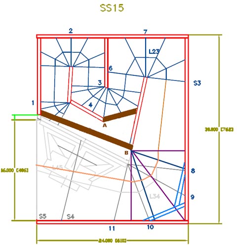
Oliver, that’s the disadvantage of writing in another language I’m afraid. About the ‘new’ reference points I think I need more explanation. It’s not your method I criticize. What I miss is accuracy that can give very important information. Therefore you need an extra 3 reference points for each bend.
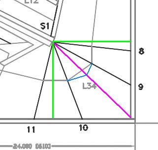
1.) 2 of them (one before the corner and one after the corner) start from the corner centre point towards the closest positions of the outlines of the bend. Normally they will hit the outlines of the path with 90 degrees (see the green lines)
2.) The other reference point starts from the centre of the bend towards the corner point. This will give the longest distance from centre to the outlines of the path (see the purple line)
If you add these 3 extra reference points it will produce a much more accurate “horizontal representation” of the real cab. In case of the SS15 it will show that the last bend is way more off the ideal path than other bends.
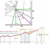
That is how I came up with the red line in your “horizontal representation” of the SS15 (instead of your dashed line). Look at the area I marked as “problem area”. You will see your dashed line is not showing the whole story. The interesting part is how steep the line is between point 9.5 and 10.5.

See, why you need EXTRA correction between reference point 10 and 11?
If you translate that to the ¼ wavelength horn path this means the area around 90Hz. This is exactly where JBell measures 1dB less and with full power it should be more then 1dB.
I got the inspiration by Xoc1 and his “horizontal representations” over the last couple of months. I told him I was following his posts with special interest so I hope he is reading this this.
The problem with putting all my suggestions in HornResp is that the BL force isn’t a stable value in relation to excursion of the voice coil (remember DJK’s remarks?). So that’s why I want extra volume at the last section of the horn. I get this extra volume by lifting the driverpanel upwards. And when the driver excursion gets around Xmax the BL factor is only 70% and the extra volume will make this up. So all these relative small 1dB corrections will be gaining more dB’s at Xmax and higher.
1.) 2 of them (one before the corner and one after the corner) start from the corner centre point towards the closest positions of the outlines of the bend. Normally they will hit the outlines of the path with 90 degrees (see the green lines)
2.) The other reference point starts from the centre of the bend towards the corner point. This will give the longest distance from centre to the outlines of the path (see the purple line)
If you add these 3 extra reference points it will produce a much more accurate “horizontal representation” of the real cab. In case of the SS15 it will show that the last bend is way more off the ideal path than other bends.
That is how I came up with the red line in your “horizontal representation” of the SS15 (instead of your dashed line). Look at the area I marked as “problem area”. You will see your dashed line is not showing the whole story. The interesting part is how steep the line is between point 9.5 and 10.5.
See, why you need EXTRA correction between reference point 10 and 11?
If you translate that to the ¼ wavelength horn path this means the area around 90Hz. This is exactly where JBell measures 1dB less and with full power it should be more then 1dB.
I got the inspiration by Xoc1 and his “horizontal representations” over the last couple of months. I told him I was following his posts with special interest so I hope he is reading this this.
The problem with putting all my suggestions in HornResp is that the BL force isn’t a stable value in relation to excursion of the voice coil (remember DJK’s remarks?). So that’s why I want extra volume at the last section of the horn. I get this extra volume by lifting the driverpanel upwards. And when the driver excursion gets around Xmax the BL factor is only 70% and the extra volume will make this up. So all these relative small 1dB corrections will be gaining more dB’s at Xmax and higher.
Last edited:
Oliver, I have made a more accurate version and gave letters to the new reference points and where they end up in the horizontal representation.
It shows how "NON gentle" this bend is in relation to the ideal path. Also it will show clearly significant loss in volume (marked as light brown area).
I hope this will clear things....
It shows how "NON gentle" this bend is in relation to the ideal path. Also it will show clearly significant loss in volume (marked as light brown area).
I hope this will clear things....
Attachments
Last edited:
Andy, that's one way of doing it  but I think it is possible within the one-sheet-challenge. And you should hear the difference clearly if you are going to its max power (less power compression in the lowest part of the bandpass).
In the 'old' days we used a reference point every 5 or 10 cm in a bend. Just to make sure corner bracing was nowhere touching the 'ideal' path. And to much off line resulted in burning your hands by steaming two layers of tri-plex and glueing/montage under pressure.
but I think it is possible within the one-sheet-challenge. And you should hear the difference clearly if you are going to its max power (less power compression in the lowest part of the bandpass).In the 'old' days we used a reference point every 5 or 10 cm in a bend. Just to make sure corner bracing was nowhere touching the 'ideal' path. And to much off line resulted in burning your hands by steaming two layers of tri-plex and glueing/montage under pressure.
Last edited:
Hi Djim,
English (or whatever that is we are speaking here in Texas) is my second language too.
Thanks for elaborating, there is one point though, in Xoc1's plot the length are entered centered on the distance line, which would be best represented in the side view by lines that are orthagonal to the acoustic centerlines of the straight horn sections. so I would suggest to use points 8-F-11 and additionally to place points in between 8 and F, and F and 11 from the halfway point between 8-F-11 to the inside of the corner. That should give close correspondence between the side view and the profile (roll-out, horizontal representation).
Well, back to the joint cement and plaster board.
Regards,
there is one point though, in Xoc1's plot the length are entered centered on the distance line, which would be best represented in the side view by lines that are orthagonal to the acoustic centerlines of the straight horn sections.
Exactly, if you want to find the acoustic centrelines. But I don't need to find it here. For this matter I want the most accurate outlines in my roll-out to see the real cab. I think that is the way to see these spots on their correct points on the horizontal axis. And I'll will show you another 'trick' that might work after you corrected a big bend.
Okay, after you used all corrections and redraw the cab you can make a new roll-out (horizontal representation of the cab).
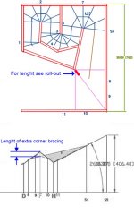
Instead of using corner bracing I was thinking of using one from the centre point! The idea behind this is that the large soundwaves don't see smaller objects so a small bracing in the centre wont hurt them. The volume it takes is almost nothing but you wont loose the volume from corner bracing on the outside of the path.
But it forces the low speed air molecules (that are using the shortest path) to raise their speed around the centre of the corner. Also it extends the shortest route within the horn. How much it works positive (or negative perhaps?) in the low end of the bandpass, I have no idea...
A few notes:
1.) It only can work in big corners.
2.) The length is set out between the difference between the ideal path (based on the reference point/line that hits the corner) and the extra length in the corner. I made it more clear in the roll-out (hor.repr.)
Any suggestions or comments?
Attachments
Last edited:
Not if you use my suggestion about lifting the driverpanel upwards. That way you can make up for some 'lost' volume in that area. Not completly, I agree on that, but enough to see changes in gain (I hope). But like I said I'm only looking for changes that fall within the one -sheet-challenge so I have to deal with that.Yes but you still have a big restriction after that at point H between points 10 and 11.
- Home
- Loudspeakers
- Subwoofers
- Single sheet TH challenge