what do you think don?
nice design JB very nice
I recognize that folding type, I'we done something simillar in this design suitable for the 15TBX100 or eighteensound 15LW1401
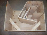
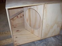
It's a pretty nice folding - I copied it off the speakerplans site and modified it slightly for use in my stepped-horn POC. On the plus side, there's minimal bends = more effective path length in the same cross section, the horn is better braced around the mouth area by the internal sections, the design allows you to either top-mount or bottom mount the driver and if you leave the top removable, you've got access to the throat area to play around with its geometry if you want to post-build.
On the minus side, unlike the folds suggested by JBell, the section that's facing the floor is near the middle of the horn rather than at the end, and if it's not properly braced, box will start to "walk" when the volume is turned up and the bass will start to sound awful (ask me how I know this, LOL). Getting the bracing right is very important in sections one (top) and three (bottom).
I was able to finish my POC with plenty of ply left over (before I started playing around with the bracing), so it should be possible make a slightly larger one without having to use more than one 4x8 sheet.
What if you can do this with a 12" driver?
Consider the Fi X12 - see https://ssl.perfora.net/www.ficarau...0_Speakers/0045_X/product_overview.shopscript.
This driver is hand-built on order, and you can actually ask for variations in its design. The base model costs $119, and its powerhandling can be increased from 250W up to 500W via the $20 BPower option.
The specs as given suggest that you can get 100 dB/2.83V/1M from 40 Hz to above 100 Hz and over 125dB in the passband without exceeding Xmax (assuming you go with the BPower option), using a TH that works out to about 4.8 cu.ft. net. This should be achievable with one 4x8 piece of ply. I assumed Le of 2.30 mH - it's likely to be less than this, and can be adjusted upwards if necessary by an external inductor.
Of course, this is all in theory...
I am not really sure what you are after here. Neither were from you, so why get so out of shape?Could you enlighten us?
I, for one, make every attempt to follow the HR sim. Of course I use CONICs and build Parabolics, but the error is small, and I know I'm off a few percent
in the corners.
When I can't follow the HR sim, I go back and update the sim with the as-built information. If the damage is too bad, I scrap the drawing.
Sims are sims, they are one dimensional equations simming a three dimensional world. We're lucky they even come close.

If you look at the designs posted at that point, and go check out the threads, what was built and measured was not what was in the HR graphs posted here.
If you have a sub built, and then design a HR sim from it, and it turns out different then your sim is wrong. If you design a sim and then build a real sub around it, if the sub measures different from the sim you didn't build the simed horn. There is nothing else to it.
If you go back though these threads you can find many examples of this. Anytime there is a design that varies when built and measured from the HR sim, if you take the time to create a new HR sim from the blueprints you will find the error, and if done correctly the sim will match up to the measured response.
That said the amplitudes may vary a little (due to realities HR doesn't handle,) but the peaks and dips will match-up Hertz for Hertz on the FR and Impedance graphs.
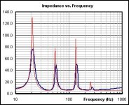
Why measuring impedance is important...
It might not be an exact match, but it should be very close.
The impedance graphs will also indicate if there are other problems with your build.
For example:
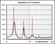
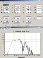
Image 1 shows the impedance response of the TH I built a few days ago. Note that while the first two impedance peaks look like fairly close matches, some things stick out: (1) the actual impedance peaks are slightly higher in frequency than the predicted ones, suggesting that the path length may be slightly shorter (I predicted the possibility of it being off by around 3%~4%). This could also possibly be due to other things, like difference between HornResp's value for c and actual c in my location. However, more important though are the greatly reduced third peak and some ripples above 100 Hz, and the difference between predicted and actual impedance between 20 and 40 Hz is a bit higher than it appears to be elsewhere in the response graph. This suggests that the enclosure is not sufficiently braced and the panels are not properly damped.
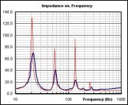
Image 2 shows the same TH, this time with a bit of bracing added to the first segment. The upper impedance peak is easier to distinguish, but it's not very high, and there are still a few ripples in the response that are not predicted by HornResp.
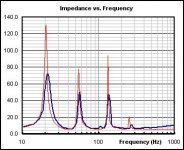
Image 3 shows the same TH, this time with a lot more bracing added to the first segment (basically an additional layer of plywood was glued and screwed to the external panel at that point). Some bracing was also added to the third segment of the horn (found at the bottom of the box). The upper peak is now higher and very clearly defined and the ripple @200 Hz has disappeared.
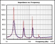
Image 4 shows the same TH, this time with more bracing added to the third segment of the horn (two 5" x 20" strips of ply added to the bottom of the box). A small brace was also added internally to the second segment of the horn. Not much has changed, but it looks like there's now closer correlation between the predicted and actual impedance between 20 and 40 Hz. Further bracing is likely not going to make any significant difference, unless I manage to find what panel resonance is causing the little blip @ 100 Hz. I might spend some time on that later today.
Image 5 shows the same TH, with 185 Lbs of weight added to the enclosure (basically me sitting on top, LOL). All panel resonances are now sufficiently damped to the point of having little or no visible impact on the impedance curve.
That said the amplitudes may vary a little (due to realities HR doesn't handle,) but the peaks and dips will match-up Hertz for Hertz on the FR and Impedance graphs.
It might not be an exact match, but it should be very close
.The impedance graphs will also indicate if there are other problems with your build.
For example:
Image 1 shows the impedance response of the TH I built a few days ago. Note that while the first two impedance peaks look like fairly close matches, some things stick out: (1) the actual impedance peaks are slightly higher in frequency than the predicted ones, suggesting that the path length may be slightly shorter (I predicted the possibility of it being off by around 3%~4%). This could also possibly be due to other things, like difference between HornResp's value for c and actual c in my location. However, more important though are the greatly reduced third peak and some ripples above 100 Hz, and the difference between predicted and actual impedance between 20 and 40 Hz is a bit higher than it appears to be elsewhere in the response graph. This suggests that the enclosure is not sufficiently braced and the panels are not properly damped.
Image 2 shows the same TH, this time with a bit of bracing added to the first segment. The upper impedance peak is easier to distinguish, but it's not very high, and there are still a few ripples in the response that are not predicted by HornResp.
Image 3 shows the same TH, this time with a lot more bracing added to the first segment (basically an additional layer of plywood was glued and screwed to the external panel at that point). Some bracing was also added to the third segment of the horn (found at the bottom of the box). The upper peak is now higher and very clearly defined and the ripple @200 Hz has disappeared.
Image 4 shows the same TH, this time with more bracing added to the third segment of the horn (two 5" x 20" strips of ply added to the bottom of the box). A small brace was also added internally to the second segment of the horn. Not much has changed, but it looks like there's now closer correlation between the predicted and actual impedance between 20 and 40 Hz. Further bracing is likely not going to make any significant difference, unless I manage to find what panel resonance is causing the little blip @ 100 Hz. I might spend some time on that later today.
Image 5 shows the same TH, with 185 Lbs of weight added to the enclosure (basically me sitting on top, LOL). All panel resonances are now sufficiently damped to the point of having little or no visible impact on the impedance curve.
Attachments
Any updates with this new design JBell?
Been busy with installs, no time to build the new single sheet design yet. I believe it will most likely be my favorite to date. I seem to end up with small things I don't like hearing out of a TH when there are too many dimensions that are too similar, and too many parallel walls. (The 150lb beast that had all dimensions of either 24" or 48" comes to mind.) This last design has none of that. I'm hopeful it will require zero reflector 'tuning.'
I just used up the last of my 'cubes.' Gymnasium theater with a 24' wide screen. One cube center court 27' in the air mounted tight to a solid concrete wall. AND as expected... my back likes me better than with the last 150lb beasts.
Iron man was silly fun... No it's not true HT low, but 40hz high pass still gets the job done, and xti amps make this kind of stuff brain dead easy.
Last edited:
Post #17
Hi jbell,
I tried your suggestion, and it defeats the purpose of that particular design by reintroducing the dip @ 160Hz. Increase S2, and you'll have to decrease S4-S5; anyway, your original design would be better for simplicity and low frequency extension.
As to the discussion about simulation v. reality: my simulation was derived from multiple iterations of the drawing, and in that particular case is about as close as I can get it. Don Snyder's drawings end up being tested builds that reflect the simulations well.
I have not had the time to look at your design from Posts #38/39/48, hope you'll get the dimensions finalized, it looks quite promising. It's amazing how many different wrinkles one can put on the same general design.
Regards,
Accurate simulation of singlesheet_2
Hi again,
After trying to reconcile the Hornresp Input w/ the drawing, and trying to draw what was there I'm at a bit of a loss. To get to a better simulation of what is actually being build I will need much better data, otherwise it's back to horseshoes and handgranates.
Regards,
Hi again,
After trying to reconcile the Hornresp Input w/ the drawing, and trying to draw what was there I'm at a bit of a loss. To get to a better simulation of what is actually being build I will need much better data, otherwise it's back to horseshoes and handgranates.
Regards,
Attachments
Oliver:
I have issues translating what I draw to hornresp as well, it only makes sense that others have the same issue....
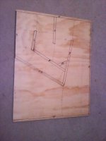
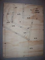
However the goal in this case was a dual taper TH with the main taper change at the upper back. My cell phone took a lousy pic the other day, so here is my layout with some additional dimensions called out.
I have issues translating what I draw to hornresp as well, it only makes sense that others have the same issue....
However the goal in this case was a dual taper TH with the main taper change at the upper back. My cell phone took a lousy pic the other day, so here is my layout with some additional dimensions called out.
Attachments
re:jbell 1 sheet layout layout = kool ! - I luv 1-sheet speaker projects
yep, so do I... And this one has the side benefit of having great looks. I'm thinking a PE square metal grill will complete the look.
Have to wait till the glue dries to know for sure what it sounds like. I glued up the 2nd side, so no tuning on this one, it is what it is. (gutsy or stupid -- don't know.)
Attachments
Thanks oliver:
It'd be nice to be able to accurately sim this, as my initial 2.83v readings are AWESOME !!!!! I won't do any 28v readings until the glue has time to set for 24hours, so take this with a HUGE grain of salt, but still...... flat 105db from 50-120... no nasty dip at 160, smooth up through 200hz, and still 99db at 40hz.
I am in love.
If anyone wonders why I post readings this way -- it's so I'm consistent back to my first measurements. This way I always have an exact reference to what I've done before. I may not be 100% accurate in my measurements, but they are consistent from one sub measurement to the next.
I use sine waves, every 1hz, over grass outdoors, and then plot out the every 5hz increments. (no one really wants to see the readings for every 1 hz.) While I have smaart and other apps, I always come back to the same spl meter, volt meter, and sine waves.
There is a sharp narrow dip from 150-152hz down to about 100db, but other than that, everything is nice and smooth.
2 Boxes or more minimum to bring up the 40hz, and it's a party.
Anyone considering building cubes forget it.. this trounces the cube. Anyone considering building the big box, unless you REALLY need sub 40hz, forget it -- build this.
Here's the numbers:
40hz 98.5
45hz 100.5
50hz 102
55hz 103.5
60hz 105
65hz 105
70hz 105
75hz 104.5
80hz 104.2
85hz 104
90hz 104
95hz 104
100hz 104.5
105hz 105
110hz 105
115hz 105.5
120hz 106.5
Thats pretty cute actually. I was looking at the original and I assume you adjusted for the saw cuts somewhere?
what does three of those stacked look like in horn response. You know me I like 3's.
Your inital numbers look better than the furysub. I like that it goes into mid bass territory.
Might be a really sweet compact system. Let us know how the cab flexes at 28v.
what does three of those stacked look like in horn response. You know me I like 3's.
Your inital numbers look better than the furysub. I like that it goes into mid bass territory.
Might be a really sweet compact system. Let us know how the cab flexes at 28v.
Last edited:
- Home
- Loudspeakers
- Subwoofers
- Single sheet TH challenge