We can exlude the EAW and the EV TX from the comparison. The EAW is a hybrid design. The EV TX uses a chassis with a terribly weak motor, combined with (too) low tuning, which leads to a pronounced drop-off in the lower end.
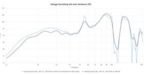
The Fulcrum is a somewhat decent comparison, and does >100 dB SPL 1w / 1m / 2pi from 50 Hz on - on average 103 dB in the bass area, very similar to the EV Xsub.
The JBL has an even more similar FR to the Xsub; sadly the datasheet lacks the information if the sensitivity value is 2pi or 4pi.
Ahh, the good old "mouth bubble" myth. "1m is near field! - you have to measure a sub at least in 3, 4 m distance"; "at 1m distance the port is much too loud!" It has taken me years to defeat this nonsense in the German forums.
Here's a FR measurement of a large ported sub in 1m vs. 10m distance (source):
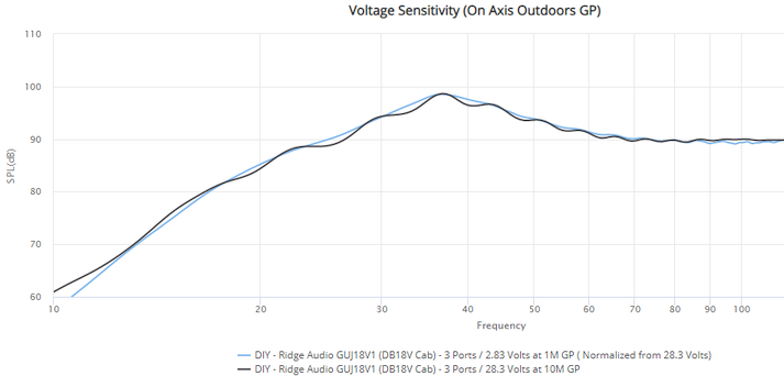
Basic response of single subs is the same from 1m onwards. There are at least three challenges with greater distances however:
1. reflections. The distance of the measurement setup to the next hard object has to be a high multiple of the distance from the speaker to the mic. At 10m measurement distance, a suitable location is very hard to find.
The 10m measurement shown above already displays some influence of reflections, indicated by waviness - an addition and substraction of reflections to / from the direct sound of the speaker, alternating with frequency / wavelength.
2. SNR. Environment noise and noise in the signal chain has to be sufficiently drowned out for meaningful results. Neglect this, and you will get a choppier curve.
Or,
3. the required high SPL can run the speaker into a (partial) limit. For example, a bassreflex sub with an undersized port will show port compression (lower relative sensitivity at / around the tuning frequency) at higher levels.
Okay. I believe we've covered some ground here. While I do find such discussions fascinating at times, and of course very useful, what seems to be required here in terms of establishing a sufficient understanding of acoustics and physics for everyone goes beyond the scope of a forum discussion. It's not what I signed up for either.
I am glad the measurements are appreciated. Some have interpreted them perfectly. For others I would recommend continued learning in theory and practice.
Again, great cab! For something almost stupid good for the money , do look into the 15LB075-UW4. The full thread for this chassis in the SS15 includes simulations, link to my measurements, and a build guide with parts list (in mm), CAD drawings and all the like; visit here -> click.
The Fulcrum is a somewhat decent comparison, and does >100 dB SPL 1w / 1m / 2pi from 50 Hz on - on average 103 dB in the bass area, very similar to the EV Xsub.
The JBL has an even more similar FR to the Xsub; sadly the datasheet lacks the information if the sensitivity value is 2pi or 4pi.
possibly due to measuring at only 1 meter, at 2 meters the test mic would be out of the “mouth bubble”.
Ahh, the good old "mouth bubble" myth. "1m is near field! - you have to measure a sub at least in 3, 4 m distance"; "at 1m distance the port is much too loud!" It has taken me years to defeat this nonsense in the German forums.
Here's a FR measurement of a large ported sub in 1m vs. 10m distance (source):
Basic response of single subs is the same from 1m onwards. There are at least three challenges with greater distances however:
1. reflections. The distance of the measurement setup to the next hard object has to be a high multiple of the distance from the speaker to the mic. At 10m measurement distance, a suitable location is very hard to find.
The 10m measurement shown above already displays some influence of reflections, indicated by waviness - an addition and substraction of reflections to / from the direct sound of the speaker, alternating with frequency / wavelength.
2. SNR. Environment noise and noise in the signal chain has to be sufficiently drowned out for meaningful results. Neglect this, and you will get a choppier curve.
Or,
3. the required high SPL can run the speaker into a (partial) limit. For example, a bassreflex sub with an undersized port will show port compression (lower relative sensitivity at / around the tuning frequency) at higher levels.
Okay. I believe we've covered some ground here. While I do find such discussions fascinating at times, and of course very useful, what seems to be required here in terms of establishing a sufficient understanding of acoustics and physics for everyone goes beyond the scope of a forum discussion. It's not what I signed up for either.
I am glad the measurements are appreciated. Some have interpreted them perfectly. For others I would recommend continued learning in theory and practice.
Again, great cab! For something almost stupid good for the money
, do look into the 15LB075-UW4. The full thread for this chassis in the SS15 includes simulations, link to my measurements, and a build guide with parts list (in mm), CAD drawings and all the like; visit here -> click.Stoneeh,The JBL has an even more similar FR to the Xsub; sadly the datasheet lacks the information if the sensitivity value is 2pi or 4pi.
Ahh, the good old "mouth bubble" myth. "1m is near field! .
Here's a FR measurement of a large ported sub in 1m vs. 10m distance
Basic response of single subs is the same from 1m onwards.
Again, great cab! For something almost stupid good for the money
Agreed, the SS15 is a great value, and packs a punch for it's size.
I'm fairly sure the JBL SRX measurements are half space, having measured the cabinet myself and compared it to my various subs, simulations, other's "sub shootouts" going back well over ten years.
JBL used to measure their subs on top of the 8400 building, see the 3/22/2004 2268 in 8 cubic foot sealed response and the SRX718 &728 responses.
Josh Ricci (DataBass) now does most of his measurements at two meters.
Close enough to avoid noise, far enough (for most cabinets) to avoid near-field effects.
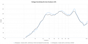
As you can see in the response of the Growler, a FLH of similar size to the SS15, the response deviations from 1 to 10 meters are near 3dB in some areas.
Josh's larger Gjallerhorn TH has only minor deviations up to 50Hz, then some exceeding 3dB above. The DSL DTS10 varies quite a bit too.
At any rate, 3dB here and there is not a big deal, but 2m testing can avoid most of those deviations often seen in horn cabinets tested at 1meter.
Cheers,
Art
Attachments
I thought that 10M @28.3V thing was more about finding out how the DUT performed at more realistic playback levels than anything else.
I suspect measuring @2M would be fine for most subs, unless the box is a really big one.
I'd love to see what the THD curve for that build looks like.
I suspect measuring @2M would be fine for most subs, unless the box is a really big one.
I'd love to see what the THD curve for that build looks like.
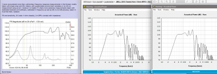
Art: the slight difference in the responses of the 1m vs the 10m measurements of the Gjallarhorn and the Danley, which are in the low bass area about 1 dB for the former, and 2 dB for the latter, can be perfectly attributed to problem #3 with large distance measurements I described in my last post.
The measurements at Data-Bass are done at 2V / 4ohm and 2,83V / 8 ohm = 1 watt for 1m distance. They are done at 20V / 4 ohm and 28,3V / 8 ohm = 100 watts for 10m distance. It is perfectly normal and expected for such a design to show some port compression at 100 watts, which would show itself by a sensitivity drop at the lower end of the frequency range. I have done extensive personal comparative measurements on that very subject, and there are also AES papers covering it.
It is in principle not possible for subwoofers of similar design to show differing near vs far field behavior. Only possible explanation would be a drastic difference in baffle size, in the area of metres, which is not the case here (only ever is with large stacks of subs).
Jfyi, I have actually measured the SS15 in 1m vs 2m, but only for the reason that I did quick initial measurement in my outer courtyard (pic in post #2227, provided only as proof that I built the sub and placed a mic in front of it), where I have to be at 1m or below to drown out reflections. The proper measurement series I did in the vineyard shown in the video over at HiFi-Forum, at 2m distance - 2m solely for the reason of reducing SPL at the mic, and via that reducing distortion influence of the mic (my Isemcon EMX-7150 can handle 135 dB @ 1% THD, but I will use the opportunity to get as near to 0% signal chain distortions as possible).
As always, with any sub I've ever done a similar comparison with, FR / sensitivity came back the same, except for some minor waviness of the courtyard measurement due to said reflections. For that reason I used the 2m measurement, scaled back to 1m (+6 dB per halfing of distance), for publication.
There was never any need to mention that, because it just doesn't make a difference. I mention it now only to inform you that your assumption on the distance I used is not true.
Same for the EV Xsub btw. - did the whole measurement series at 2m, scaled the values to 1m for publication.
Brian: if you mean the SS15 w. 15LB075, a Max. SPL @ 10% THD (a commonly used yardstick) chart can be found at my linked report @ HiFi-Forum.de.
BTW, the "effortless" sound that you experienced with your SS15 build is similar to what I experienced with my TH builds. Seems to be a feature of the design, and likely due to the very low dynamic compression - I measured as little as 0.3dB in my POC3 build up to the 10% THD level. The THD "profile" is also interesting - while there are the expected dip in 3rd order HD at or near the lowest frequency where cone motion is at a minimum, what happens to the THD above that is curious IMO, and I think highly influenced by the out of band resonances.
Attachments
Brian, indeed. "Normalized from 28,3V" would mean that the sub was measured at the same voltage at 1m distance, then scaled to 1m / 2 or 2,83V.
Well, that rules out my possible explanation of the difference being port compression.
Again though, some of his subs measured at 1 vs 10m distance, like the Ridge Audio GUJ18V1 build I linked, show no drop in SPL at 10m. Some do.
Physics do not allow for such a difference between boxes of inconsequental baffle size differences at those frequencies. So we would need detailed information on his whole measurement setup to diagnose where the differences stem from.
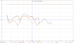
Also, as mentioned, I have my own data on this. I will share one measurement series, of a single 18" BR sub. The environment is my garden, with the next hard obstacle being a small garden hut 10, 15 metres away; then at least another 20 metres of nothing, except grass and small trees.
Gold represents 0,5m, red 1m, blue 2m, green 4m distance from speaker to mic. SPL at the mic was maintained equal by increasing the input to the sub.
As we can see, no difference in bass response between 0,5 and 2m. 4m gets choppier, because of reflections, but is on average equal to the other distances in the bass area.
I have done multiple of those comparisons, and all I ever find at greater distances is choppiness / waviness due to noise and reflections - never an inherently different response.
As for the subjective impression of the SS15 vs. measurements: I would instinctively say that the large resonator should lead to little compression. However, at tuning (43 Hz) my SS15 has a sensitivity of almost exactly 100 dB. It reaches a Max. SPL @ 10% THD of 123 dB at that frequency. That required an input of what I measured to be around 50 volts, 600 watts. That suggests a power compression of about 4 dB.
Then again,
- power compression is largely determined by the chassis
- electrical / thermal power compression will be different with music, which has a much lower energy density than sine wave test signals
In the end, I am satisfied having measured high sensitivity, high max. SPL, and having a very satisfying listening experience. I personally do not need to dig deeper.
Well, that rules out my possible explanation of the difference being port compression.
Again though, some of his subs measured at 1 vs 10m distance, like the Ridge Audio GUJ18V1 build I linked, show no drop in SPL at 10m. Some do.
Physics do not allow for such a difference between boxes of inconsequental baffle size differences at those frequencies. So we would need detailed information on his whole measurement setup to diagnose where the differences stem from.
Also, as mentioned, I have my own data on this. I will share one measurement series, of a single 18" BR sub. The environment is my garden, with the next hard obstacle being a small garden hut 10, 15 metres away; then at least another 20 metres of nothing, except grass and small trees.
Gold represents 0,5m, red 1m, blue 2m, green 4m distance from speaker to mic. SPL at the mic was maintained equal by increasing the input to the sub.
As we can see, no difference in bass response between 0,5 and 2m. 4m gets choppier, because of reflections, but is on average equal to the other distances in the bass area.
I have done multiple of those comparisons, and all I ever find at greater distances is choppiness / waviness due to noise and reflections - never an inherently different response.
As for the subjective impression of the SS15 vs. measurements: I would instinctively say that the large resonator should lead to little compression. However, at tuning (43 Hz) my SS15 has a sensitivity of almost exactly 100 dB. It reaches a Max. SPL @ 10% THD of 123 dB at that frequency. That required an input of what I measured to be around 50 volts, 600 watts. That suggests a power compression of about 4 dB.
Then again,
- power compression is largely determined by the chassis
- electrical / thermal power compression will be different with music, which has a much lower energy density than sine wave test signals
In the end, I am satisfied having measured high sensitivity, high max. SPL, and having a very satisfying listening experience. I personally do not need to dig deeper.
Stoneeh,Brian, indeed. "Normalized from 28,3V" would mean that the sub was measured at the same voltage at 1m distance, then scaled to 1m / 2 or 2,83V.
Well, that rules out my possible explanation of the difference being port compression.
As for the subjective impression of the SS15 vs. measurements: I would instinctively say that the large resonator should lead to little compression. However, at tuning (43 Hz) my SS15 has a sensitivity of almost exactly 100 dB. It reaches a Max. SPL @ 10% THD of 123 dB at that frequency. That required an input of what I measured to be around 50 volts, 600 watts. That suggests a power compression of about 4 dB.
Finding your measurements of the SS15 were at 2m rules out sensitivity differences likely due to proximity effects.
15LB075-UW4 has very low Mms, and Xmax of only 4mm. At high drive levels, the light cone will flex, limiting output at Fb, and excursion will hardly exceed Xmax regardless of voltage input as the Bl curve drops sharply, “way more power, way less push”.
The Xmax and cone stiffness limitations, rather than (but not exclusive of) power compression caused by voice coil heating/impedance rise are probably the main limits to Maximum SPL using the 15LB075-UW4.
The B&C 15SW100 would not run into those limitations at levels far exceeding (well over +6dB) the 15LB075-UW4.
Hornresp simulations (within Xmax) for most well-built cabinets agree quite closely with their 2 pi/ground plane measurements, Josh Ricci’s DataBass has many examples we both have referenced.
Your measurements show a sensitivity around +8dB at 40 Hz , +4 dB at 100Hz greater than it’s Hornresp simulation, which is quite unusual.
Since you have ruled out measurement calibration issues, do you have any explanation for the large sensitivity/simulation variance?
Cheers,
Art
Attachments
Ground plane IS half space / 2pi. And of course this does represent "real life", since subwoofers are in the vast majority of cases ground stacked.
You might be referencing full space / 4pi, which would represent flown subwoofers. This is done only in large venues and large commercial systems and is very unlikely to ever happen to a SS15
Jfyi, a point source with omnidirectional directivity, which a single subwoofer at the bottom end of its frequency range is, loses 6 dB SPL (sound pressure level) per doubling of space - not 3 dB.
4pi (flown) = 0 dB gain
2pi (ground without wall, or flown with wall) = 6 dB gain
1pi (ground & wall) = 12 dB gain
0,5 pi (corner) = 18 dB gain
You might be confusing sound power level with sound pressure level. The gain from halfing of space in sound power level would indeed be 3 dB.
Sound power is the cause of sound pressure, and an intangible quantity that cannot be measured.
What a microphone measures is sound pressure level. Acoustic measurements done in half space yield 6 dB higher values than done in full space (again, only valid for an omnidirectional source).
Not my first rodeo. Been designing loudspeakers since the late 80's and drivers since the late 90's. I work as a consultant. Look carefully there are a lot of comparisons. To directly compare a 2Pi measurement to a ground plane measurement the mic has to be 2 meters from the loudspeaker. And the loudspeaker should be tilted toward the mic about 10 degrees.Attached is one of the papers that shows how to do a ground plane measurement properly. Interesting how it is a near perfect correlation to an anechoic up to about 13 kilohertz. Meaning it is quite useful for things other than low frequency measurements.
Attachments
do you have any explanation for the large sensitivity/simulation variance
A simple simulation, like Hornresp, bbox, BoxSIM, WinISD and the like, is a rough approximation of a speaker's response. It is a guideline that helps us build prototypes that aren't that far off the final result. It would be pure coincidence if it perfectly equated to an acoustic measurement however.
For more accurate results, one will have to use professional CAD-like software like ABEC, Comsol, ...
Hornresp simulations (within Xmax) for most well-built cabinets agree quite closely with their 2 pi/ground plane measurements, Josh Ricci’s DataBass has many examples we both have referenced.
No they don't. That's just another of your convoluted off-base claims that maybe would fly if noone bothered checking.
One quick example: the Othorn. Simulations can be found here, measurements here.
Simulated f3 is about 29 Hz; measured f3 is about 32 Hz
Simulated 1w / 1m / 2pi sensitivity is on average below 100 Hz 97 dB; measured sensitivity is 100 dB
Finding your measurements of the SS15 were at 2m rules out sensitivity differences likely due to proximity effects.
There was never any indication there should be a difference. Only in the extreme near field, way below 1m, we can ever expect a significantly different result.
The formula for deriving near field values is largest box diameter in metres squared, multiplied by frequency, divided by 340.
For the SS15, at 100 Hz, that is 17 cm. Below that, significantly less.
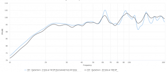
For further clarification, here's a comparison of the measurements of the SS15 I described in post #2244 - 1m GP / 1w done in my courtyard (blue) vs 2m GP / 1w done in the vineyard (scaled to 1m via adding 6 dB):
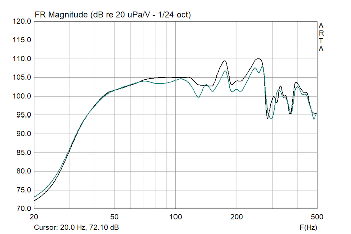
As we can see, the curves match perfectly up to 60 Hz; from there on, as mentioned, reflections distort the 1m courtyard measurement.
The fact that +6 dB for the 2m measurement equals the 1m measurement alone proves that both distances are out of the near field for this box - within the near field, doubling the distance only results in a 3 dB, not 6 dB, loss (that's why LAs work so well - they extend the near field, resulting in less SPL loss per distance than with a point source).
To directly compare a 2Pi measurement to a ground plane measurement the mic has to be 2 meters from the loudspeaker. And the loudspeaker should be tilted toward the mic about 10 degrees.Attached is one of the papers that shows how to do a ground plane measurement properly. Interesting how it is a near perfect correlation to an anechoic up to about 13 kilohertz. Meaning it is quite useful for things other than low frequency measurements.
Okay, now things are getting clearer. Based on what's presented in the linked paper, I assume your definition of "2pi measurement" is "speaker flush in the ground, pointing upwards, mic suspended in the air pointing downwards"?
The difference to my understanding of 2pi as both mic as well as speaker placed on the ground, horizontally instead of vertically, should be negligible at low frequencies. The ground would act as a mirror source in both scenarios. There might be a slight phase difference between sources to the mic in both scenarios, but with wave lenghts in the area of metres, it should be inconsequential.
What best represents "real life" between the two, as you alluded to in post #2237, good question. In real life situations, the speaker, or stacks of speakers, are placed not flush with the ground, but on the ground, in heights of usually ~0,5 to 2m. The measurement instrument, our ears
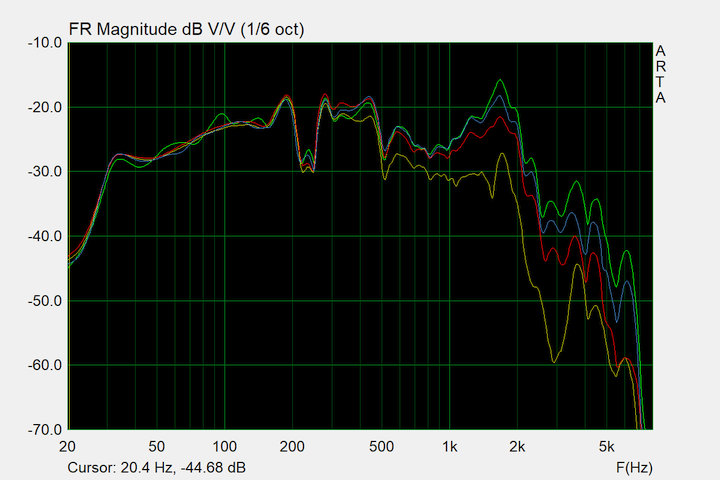
, are approximately at 1,5 to 2m height. I suppose both methods should provide a close enough representation of real life situations.As for the need of the mic to be tilted in GPMs, see the measurement in my post #2247. Neither mic nor speaker were tilted to each other in this comparison; both were lying flush on the floor.
We can see that from base tones (around a couple hundred Hz) upwards, differences begin to appear between the various distances (= angles), which get to be pronounced in midrange frequencies. This is because of the increased directivity of the large 18" speakers at higher frequencies.
Bass (generally defined as up to 200 Hz) response is unaffected, as it should and must be, because of its omnidirectional nature. So no, for bass GPMs, mic and speaker do not need to be angled to each other.
As for GPMs being useful until high frequencies: from what I gather, GPMs have established themselves as standard even for fullrange speakers with various test magazines. The requirement for that is a perfectly flat floor, and perfect angling of mic to speaker. At wavelengths of centimeters at high frequencies, even half a cm placement error can cause a significant deviation in the measurement.
Okay, now things are getting clearer. Based on what's presented in the linked paper, I assume your definition of "2pi measurement" is "speaker flush in the ground, pointing upwards, mic suspended in the air pointing downwards"?
The difference to my understanding of 2pi as both mic as well as speaker placed on the ground, horizontally instead of vertically, should be negligible at low frequencies. The ground would act as a mirror source in both scenarios. There might be a slight phase difference between sources to the mic in both scenarios, but with wave lenghts in the area of metres, it should be inconsequential.
What best represents "real life" between the two, as you alluded to in post #2237, good question. In real life situations, the speaker, or stacks of speakers, are placed not flush with the ground, but on the ground, in heights of usually ~0,5 to 2m. The measurement instrument, our ears , are approximately at 1,5 to 2m height. I suppose both methods should provide a close enough representation of real life situations.
As for the need of the mic to be tilted in GPMs, see the measurement in my post #2247. Neither mic nor speaker were tilted to each other in this comparison; both were lying flush on the floor.
We can see that from base tones (around a couple hundred Hz) upwards, differences begin to appear between the various distances (= angles), which get to be pronounced in midrange frequencies. This is because of the increased directivity of the large 18" speakers at higher frequencies.
Bass (generally defined as up to 200 Hz) response is unaffected, as it should and must be, because of its omnidirectional nature. So no, for bass GPMs, mic and speaker do not need to be angled to each other.
As for GPMs being useful until high frequencies: from what I gather, GPMs have established themselves as standard even for fullrange speakers with various test magazines. The requirement for that is a perfectly flat floor, and perfect angling of mic to speaker. At wavelengths of centimeters at high frequencies, even half a cm placement error can cause a significant deviation in the measurement.
You understand 2Pi correctly.
And that is what almost every program that simulates loudspeakers creates in sim land.
The tilting the loudspeaker. Not the mic is a recommended practice. It does make a difference in some conditions so if you want to avoid problems use the little trick.
It very well could be that your differences ion measurement between Hornresp as a simulation are related to this discrepancy. I have used HOrnresp for about 20 years. And I can tell you that if you are much different than a few db you have either really buggered the simulation or you have buggered up your enclosure. 99% of the time it is a difference in the enclosure versus the simulated enclosure. Hornresp is very accurate.
Last point. Hornresp simulates Power response. Not SPL. You have to take that into consideration to.
I take it from a few of your comments that you have live sound experience. Power response is what you are after in that business, as much as in home stereo. It what you get in the real world. Inside is generally 1Pi unless you are in a concrete block room like in Europe. Or a basement in North America. Or an apartment building I guess. Standard wood stud wall construction in North America is almost invisible a little below 30 hertz. It's the mass not wanting to move around to much that keeps the sound inside the venue. Or not!
Stoneeh,I haven't measured any other THs. In fact this is the first I've built. I have only ever listened to one other too, the Lambda Labs DH18. Data-Bass.com does have a measurement on the Othorn, and perhaps others.
Outdoor the sensitivity also really helps - large stacks on small generators very much possible.
I suppose that's why I'm posting here - if I was like "meh" after measuring and listening to the box, I wouldn't have bothered. But what I've measured and heard did leave me quite excited
Sharing your excitement after building and measuring your first tapped horn has brought back memories of hundreds of outdoor comparative tests of many different TH, BR, and FLH conducted near the time 10 years ago when this thread, and the SS15 started.
Our tests conclusively confirm the on-axis sensitivity advantage of the TH over BR.
Tapped Horn Vs. Bass Reflex Case Study
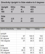
Some of the sensitivity advantage seems to be due to the TH having a higher DI (directivity index) over it’s usable pass-band. JBell’s directivity tests appear to indicate the SS15 has a higher DI to a lower frequency than my larger, longer path length Keystone TH. My directivity tests were not accurate due to proximity to surrounding buildings.
Tapped Horn Directivity
Though JBell’s directivity tests linked in the OP may have been distant from surroundings, they are rather limited in data points, and have no comparative results.
Cardioid sub arrays have become increasingly popular in the last decade, the ability of a TH to exhibit some degree of that behavior is another of it’s compelling features.
Subjective accounts of TH attenuated rear response are many, but measurements are few.
You seem to have a large open space available for testing, would you consider doing a series of polar measurements on your SS15?
Thanks,
Art
Attachments
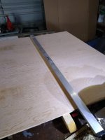
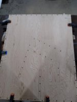
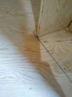
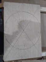
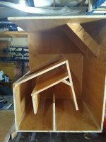
This was a really fun project, I built it up with a kappalite 3015lf (4ohms) to put on my bike trailer, I had 22 inches of space on the trailer so it was a snug fit. This is my first scratch built speaker and I made a few mistakes, I think the speaker baffle should have extended passed the backboard so I had to use the driver to keep the board together for gluing, and the holes on the second side did not line up so I ended up patching and re-drilling. Currently running it off a GM-DX874 (300 watts RMS x 2 bridged at 4 ohms) and it's very loud. The tops need be redone next. I can give it a few burps with my Umik-1 if anyone is interested.
Attachments
-
 IMG_20210608_170807052.jpg375.9 KB · Views: 426
 -
 IMG_20210608_194733672.jpg294.7 KB · Views: 390
 -
 IMG_20210610_135359528.jpg298.8 KB · Views: 399
 -
 IMG_20210610_135243517.jpg325.4 KB · Views: 429
 -
 IMG_20210614_115802362.jpg409.3 KB · Views: 232
 -
 IMG_20210615_172015937.jpg441.4 KB · Views: 237
 -
 IMG_20210619_190947743.jpg643.8 KB · Views: 220
All greetings !!! 
Guys tell me what project to build SS 15 ?
Loudspeakers 1
Nominal diameter 15 "
Nominal impedance 8 Ohm
Power AES 1200 W
Frequency range 35-500Hz
Sensitivity 98 dB / W / m
Voice coil diameter 102 mm
Voice coil height 26mm (double sided)
Wire material Copper
Frame material Kapton
Magnetic gap height 12 mm
Magnetic flux in the gap 1.2Т
Magnet material Neodymium
Frame material Aluminum
Demodulation AL Ring
Fs = 35 Hz
Re = 5.00 ohms[dc]
Le = 1.06 mH
Qt = 0.21
Qes = 0.22
Qms = 4.5
Mms = 170 grams
Rms = 8.3 kg/s
Cms = 0,12 mm/N
Vas = 134 liters
Sd = 881.41 cm^2
Bl = 29 Tm
ETA = 2.2 %
Lp(1W/1m) = 98 dB
Хmах +/-10.6 мм
Loudspeakers 2
Nominal diameter 15 "
Nominal impedance 4 Ohm
AES power 1500 W
Frequency range 35-500Hz
Sensitivity 99.5 dB / W / m
Voice coil diameter 102 mm
Voice coil height 26mm (double sided)
Wire material Copper
Frame material Kapton
Magnetic gap height 16 mm
Magnetic flux in the gap 1.35Т
Magnet material Neodymium
Frame material Aluminum
Demodulation AL Ring
Fs = 34 Hz
Re = 3.00 ohms[dc]
Le = 0.87 mH
Qt = 0.1
Qes = 0.11
Qms = 4.4
Mms = 190 grams
Rms = 9.3 kg/s
Cms = 0,115 mm/N
Vas = 127 liters
Sd = 881.41 cm^2
Bl = 33.5 Tm
ETA = 4.1 %
Lp(1W/1m) = 99.5 dB
Хmах +/-9.8 мм
I just built two SS15 cabinets - I have them loaded with one 3015LF 8ohm each.
I plan to wire these in parallel to achieve a 4ohm load on my amplifier. What should my voltage be limited to on my amplifiers DSP?
(I will be checking on the outputs with a meter, not relying on the setting in the dsp)
I plan to wire these in parallel to achieve a 4ohm load on my amplifier. What should my voltage be limited to on my amplifiers DSP?
(I will be checking on the outputs with a meter, not relying on the setting in the dsp)
Right now I have it crossed at 35Hz to 125Hz and have been testing it out with a limit set around 30+- volts.
I am using a Yamaha PX3 - to achieve around 30 volts I have it set to 600watts @ 8ohms in the limiter setting.
I have built BFM Titan 48s before and had them limited to 60 volts per Bills plans.
I am using a Yamaha PX3 - to achieve around 30 volts I have it set to 600watts @ 8ohms in the limiter setting.
I have built BFM Titan 48s before and had them limited to 60 volts per Bills plans.
- Home
- Loudspeakers
- Subwoofers
- Single sheet TH challenge