Hi,
At the moment I am designing a small system for friend as a side project.
I wanted a bass cab that was relatively compact, efficient, a width of 290mm and Flat for the octave covering 50-100hz.
I decided after reading a few threads on hear covering smaller tapped success stories I thought i would through a few numbers into horn response and see what came of it.
Firstly the main (full range) cab consists of 1 x 8nmb420 + 1 x 8cx400. I have designed it to be a three way cabinet, actively driven from 3 channels of TK2050 amp boards (amp + active crossovers internally mounted).
This means that there is 1 spare amp channel of around 50w 8r/100w 4r to drive the separate bass Cab (small speakon link out from the main cab).
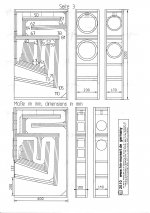
Well enough digressing!! Here is the tapped horn i have come up with.
I would be interest in feed back/criticism or even alternate driver cab combination's that fit the brief!!
At the moment I am designing a small system for friend as a side project.
I wanted a bass cab that was relatively compact, efficient, a width of 290mm and Flat for the octave covering 50-100hz.
I decided after reading a few threads on hear covering smaller tapped success stories I thought i would through a few numbers into horn response and see what came of it.
Firstly the main (full range) cab consists of 1 x 8nmb420 + 1 x 8cx400. I have designed it to be a three way cabinet, actively driven from 3 channels of TK2050 amp boards (amp + active crossovers internally mounted).
This means that there is 1 spare amp channel of around 50w 8r/100w 4r to drive the separate bass Cab (small speakon link out from the main cab).
Well enough digressing!! Here is the tapped horn i have come up with.
I would be interest in feed back/criticism or even alternate driver cab combination's that fit the brief!!
An externally hosted image should be here but it was not working when we last tested it.
An externally hosted image should be here but it was not working when we last tested it.
I'm still trying to catchup with my understanding of the TH but, as far as I understand currently... Raising the inductance [adding an inductor, coil, whatever you want to call it] you are simple adding a 1st order lowpass filter. Since Hornresp doesn't allow ext. components as far as I know. Does this actually have a place in a real-world built design or is it null/pointless when using a real active filter?
Just read through what i posted last night.
Do excuse the bad grammar and miss pelt words.
It was late!!
I should also add that the screen shot showing excursion is taken at 50w, 8r in half space, as is the spl graph showing 115db output in band.
TundraLTD
I am relatively new to Tapped horn theory myself (had always ruled it out for sound quality purposes). Maybe wrongly so? We will see soon! Also for this design compact efficiency is the name of the game.
As for whether adding the inductor to flatten response could be duplicated with processing is also a question I have been wondering?
Maybe some of the TH veterans will be able to shed light on this?
sosx
Hello,
i constructed a double bass horn with this driver,
useful 34-200 Hz and the possibility of a 6 dB crossover,
have a look:
i think your approach will work not better than a simple BR for this driver,
but test it, down to 50 Hz is to much work for the enclosure.
Your max. SPL is a bit optimistic if you see the membran movement.
Attachments
Last edited:
Hi hm
Hi hm,
Thanks for the reply.
I should point out again that they will only have
a maximum of 50w into 8r realistically. The peak displacement
at this power, peaks at 6.3mm at 57hz. In the real world
the displacement should be less (due to not applying a constant voltagensine wave). I would think very close to 5.5mm xmax. This has been shown both here and in my own reaserch in pro audio designs.
As for a br achieving the same! You could achieve the same output in this volume, but not without using twice the no of drivers and 1.5-2 times the amount of power! Which is not available. Also to achieve the f3 of 43hz means tuning the box well bellow drivers fs, which provides an uneven impedance plot and over extended (peaky) response from 45-70hz.
Your design it is a dual tuned rear loaded horn right?
Shurely this design must be an impedance and phase nightmare?
With the three different radiating surfaces all with different acoustic lengths!
I have personally never liked the sound of rear loaded horns!
Last edited:
sosx
"Shurely this design must be an impedance and phase nightmare?"
may be you don´t understand my double horns,
take a look on my HP,
and compair it with you Imp and membranmovement.
between 89-92 i worked in a disco the amps never turn over 5 !! W
as i see your simu you will have 5 mm at 1 W between 60-80 Hz,
but if you believe, test it an show us the dynamic compression, good luck.
I'm still trying to catchup with my understanding of the TH but, as far as I understand currently... Raising the inductance [adding an inductor, coil, whatever you want to call it] you are simple adding a 1st order lowpass filter. Since Hornresp doesn't allow ext. components as far as I know. Does this actually have a place in a real-world built design or is it null/pointless when using a real active filter?
Series inductors do work to flatten a response, I have measured a tapped horn with and without. The added series impedance "puts the brakes" on the resonant peaks in a tapped horn.
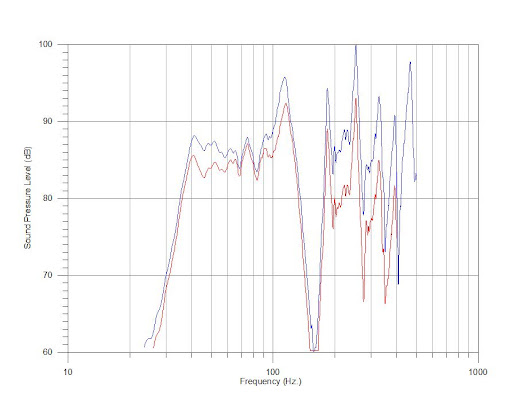
Red = inductor, Blue = no inductor. The peaks are cut more than the rest, so it is not a simple low-pass filter in this application. Parametric EQ could do the same, no doubt.
No free lunch though - what are you giving up to get that flat response?
Efficiency. There is an increase in series resistance - that's the difference between the red and the blue lines. There may also be transient response issues, but that is beyond what I can measure with my current gear. If I can't measure it, I try not to talk about it.
Hi hm,
I think I may know where your confusion lies!
As I have stated a couple of times. The peak excursion/membrane
movement hs screenshot is with 50w nominal input. Maybe the way I laid
the screen shots out had confused you?
The excursion at 1 watt is bellow 1mm!!
I must say I am not clear what you are trying to achieve with the double rear
horn designs? I couldn't find any predicted or measured
plots for these cabs, do you have any? I understand horn theory well
and can only see major issues occurring! Maybe I am missing something?
But in the pro world these wouldn't ever get considered as an option!
Tinymike- thanks for the measured plots it is nice to see the theory in operation!
Does any body else on here have any coments/opinions or ideas on improving the design?
Are there any mistakes In the design?
Kind regards
Are there any mistakes In the design?
Don't know if it's a mistake per se, just normally the expansion of a simple pipe horn expands along its entire length, so would be something like this:
GM
Edit, just noticed the added inductance which you don't need. BTW, if you add inductance you should add its Dcr in the Rg field.
Attachments
Last edited:
Series inductors do work to flatten a response, I have measured a tapped horn with and without. The added series impedance "puts the brakes" on the resonant peaks in a tapped horn.
What type of signal are you using to test? (pink noise, sine sweep, etc.)
Are you using any active HP or LP filters during your tests?
^sosx
Hello,
may be your plot was the point,
you saw all my double horns with measurement,
and you saw they are all the "same", so my study
is simulated the same, so it will work.
How much watt makes a normal amp 50- 5kwatt (log volume control)
when you open it at 12 o´clock? --- it is only 10 W peak!
As i said in the disco i worked 89-92 all amps never open over 11 o´clock (5Wpeak)
For pro audio check out my PA studies, simply the same as my other double horns.
What type of signal are you using to test? (pink noise, sine sweep, etc.)
Are you using any active HP or LP filters during your tests?
Swept sine signals with Room EQ Wizard or HolmImpulse
No filters, the electronics measure flat through the data I've presented.
Measured outdoors in a quasi-2PI environment - it was raining on and off that night, can't remember how we had this particular sub set up. No change in gain between sweeps, set at 2.00 volts into a 4-ohm resistance. The only thing I did between the sweeps was insert the inductor in series with the positive speaker lead.
- Status
- This old topic is closed. If you want to reopen this topic, contact a moderator using the "Report Post" button.
- Home
- Loudspeakers
- Subwoofers
- 18 Sound 8NMB420 tapped horn