A year ago I posted an Akabak model of a triple reflex bandpass. This is the thing that Bose used to use in their "Acoustimass" subs. (They switched to a transmission line a few years ago.)
Does anyone know if it's possible (or reasonable) to combine a bandpass with a tapped horn? In other words, a subwoofer with two chambers. The first chamber is a tapped horn. The second chamber is fed by the tapped horn, and has a port. The mass of air in the second chamber is an acoustic low pass, and reduces distortion. It also resonates, and that reduces excursion. (A fourth excursion minimum.)
Here's my idea:
Is this loony?
I know that I could "test" the theory with an Akabak model. But making one would take me a couple of hours.
Is this a crazy idea?
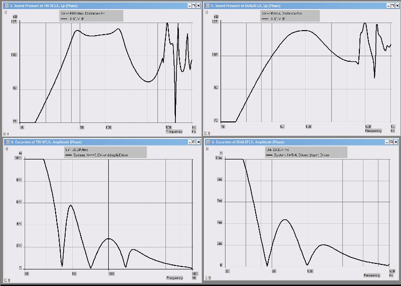
In the meantime, here's my triple reflex model, along with some sims. You can see that the triple reflex is complex, but it definitely reduces excursion and distortion.
System 'S1'
|================================================= ================================================== =====
|REQUIRED AKABAK SETTINGS:
|File > Preferences > Physical system constants:
|Sound velocity c = 344m/s
|Medium density rho = 1.205kg/m3
|Sum > Acoustic power:
|Frequency range = 10Hz to 20kHz
|Points = 533
|Input voltage = 2.83V rms
|Integration = 2Pi-sr
|Integration steps = 1 degree ... 1 degree
|Integration method = Cross
|================================================= ================================================== =====
Def_Const |Hornresp Input Parameter Values
{
|Length, area and volume values converted to metres, square metres and cubic metres:
Rg = 0.01e-0; |Amplifier output resistance (ohms)
S1 = 182.37e-4; |Horn segment 1 throat area (sq cm)
S2 = 364.74e-4; |Horn segment 1 mouth area and horn segment 2 throat area (sq cm)
S3 = 547.11e-4; |Horn segment 2 mouth area and horn segment 3 throat area (sq cm)
S4 = 729.48e-4; |Horn segment 3 mouth area (sq cm)
L12 = 8.00e-2; |Horn segment 1 axial length (cm)
L23 = 8.00e-2; |Horn segment 2 axial length (cm)
L34 = 8.00e-2; |Horn segment 3 axial length (cm)
Vrc = 28.32e-3; |Rear chamber volume (litres)
Lrc = 25.4e-2; |Rear chamber average length (cm)
Ap = 81.05e-4; |Rear port cross-sectional area (sq cm)
Lpt = 34.92e-2; |Rear port tube length (cm)
Vtc = 18240.00e-6; |Front chamber volume (cc)
Atc = 550.00e-4; |Front chamber cross-sectional area (sq cm)
Ata = 182.35e-4; |Front port cross-sectional area (sq cm)
Tpt = 18.00e-2; |Front port tube length (cm)
V3c = 56.32e-3; |Third chamber volume (litres)
L3c = 30.0e-2; |Third chamber average length (cm)
|Parameter Conversions:
Sd = 550.00e-4; |Diaphragm area (sq cm)
Arc = Vrc / Lrc;
Ltc = Vtc / Atc;
A3c = V3c / L3c;
}
|================================================= ================================================== =====
|Network node numbers for this horn-loaded vented-box system:
|0-Voltage-1-Resistance-2
| |
| 3-Chamber-4-Driver-5-Chamber-7-Port-12-Chamber-8-Segment-9-Segment-10-Segment-11-Radiator(1)
| |
| --------Port--------------------------
|================================================= ================================================== =====
Def_Driver 'Driver'
Sd=550.00cm2
Bl=20.12Tm
Cms=1.0E-04m/N
Rms=5.66Ns/m
fs=53.83Hz |Mmd = 74.30g not recognised by AkAbak, fs calculated and used instead
Le=0.67mH
Re=5.23ohm
ExpoLe=1
System 'System'
Resistor 'Amplifier Rg'
Node=1=2
R={Rg}
Driver Def='Driver''Driver'
Node=2=0=4=5
Duct 'Rear Port'
|Node=4=3=12
Node=3=12
SD={Ap}
Len={Lpt}
Visc=0
Duct 'Rear chamber'
Node=4=3
SD={Arc}
Len={Lrc}
Visc=0
Duct 'Front chamber'
Node=5=7
SD={Atc}
Len={Ltc}
Visc=0
Duct 'Front Port'
Node=7=12
SD={Ata}
Len={Tpt}
Visc=0
Duct 'Third chamber'
Node=12=8
SD={A3c}
Len={L3c}
Visc=0
Waveguide 'Horn segment 1'
Node=8=9
STh={S1}
SMo={S2}
Len={L12}
Conical
Waveguide 'Horn segment 2'
Node=9=10
STh={S2}
SMo={S3}
Len={L23}
Conical
Waveguide 'Horn segment 3'
Node=10=11
STh={S3}
SMo={S4}
Len={L34}
Conical
Radiator 'Horn mouth'
Node=11
SD={S4}
Does anyone know if it's possible (or reasonable) to combine a bandpass with a tapped horn? In other words, a subwoofer with two chambers. The first chamber is a tapped horn. The second chamber is fed by the tapped horn, and has a port. The mass of air in the second chamber is an acoustic low pass, and reduces distortion. It also resonates, and that reduces excursion. (A fourth excursion minimum.)
Here's my idea:
- A tapped horn has relatively wide bandwidth, high efficiency, and three excursion minimums.
- A triple reflex bandpass box has narrow bandwidth, high efficiency, and three excursion minimums.
- If one combined both, you could potentially get a fourth excursion minimum, and a reduction in distortion via the acoustic filtering of a bandpass enclosure.
Is this loony?
I know that I could "test" the theory with an Akabak model. But making one would take me a couple of hours.
Is this a crazy idea?
In the meantime, here's my triple reflex model, along with some sims. You can see that the triple reflex is complex, but it definitely reduces excursion and distortion.
System 'S1'
|================================================= ================================================== =====
|REQUIRED AKABAK SETTINGS:
|File > Preferences > Physical system constants:
|Sound velocity c = 344m/s
|Medium density rho = 1.205kg/m3
|Sum > Acoustic power:
|Frequency range = 10Hz to 20kHz
|Points = 533
|Input voltage = 2.83V rms
|Integration = 2Pi-sr
|Integration steps = 1 degree ... 1 degree
|Integration method = Cross
|================================================= ================================================== =====
Def_Const |Hornresp Input Parameter Values
{
|Length, area and volume values converted to metres, square metres and cubic metres:
Rg = 0.01e-0; |Amplifier output resistance (ohms)
S1 = 182.37e-4; |Horn segment 1 throat area (sq cm)
S2 = 364.74e-4; |Horn segment 1 mouth area and horn segment 2 throat area (sq cm)
S3 = 547.11e-4; |Horn segment 2 mouth area and horn segment 3 throat area (sq cm)
S4 = 729.48e-4; |Horn segment 3 mouth area (sq cm)
L12 = 8.00e-2; |Horn segment 1 axial length (cm)
L23 = 8.00e-2; |Horn segment 2 axial length (cm)
L34 = 8.00e-2; |Horn segment 3 axial length (cm)
Vrc = 28.32e-3; |Rear chamber volume (litres)
Lrc = 25.4e-2; |Rear chamber average length (cm)
Ap = 81.05e-4; |Rear port cross-sectional area (sq cm)
Lpt = 34.92e-2; |Rear port tube length (cm)
Vtc = 18240.00e-6; |Front chamber volume (cc)
Atc = 550.00e-4; |Front chamber cross-sectional area (sq cm)
Ata = 182.35e-4; |Front port cross-sectional area (sq cm)
Tpt = 18.00e-2; |Front port tube length (cm)
V3c = 56.32e-3; |Third chamber volume (litres)
L3c = 30.0e-2; |Third chamber average length (cm)
|Parameter Conversions:
Sd = 550.00e-4; |Diaphragm area (sq cm)
Arc = Vrc / Lrc;
Ltc = Vtc / Atc;
A3c = V3c / L3c;
}
|================================================= ================================================== =====
|Network node numbers for this horn-loaded vented-box system:
|0-Voltage-1-Resistance-2
| |
| 3-Chamber-4-Driver-5-Chamber-7-Port-12-Chamber-8-Segment-9-Segment-10-Segment-11-Radiator(1)
| |
| --------Port--------------------------
|================================================= ================================================== =====
Def_Driver 'Driver'
Sd=550.00cm2
Bl=20.12Tm
Cms=1.0E-04m/N
Rms=5.66Ns/m
fs=53.83Hz |Mmd = 74.30g not recognised by AkAbak, fs calculated and used instead
Le=0.67mH
Re=5.23ohm
ExpoLe=1
System 'System'
Resistor 'Amplifier Rg'
Node=1=2
R={Rg}
Driver Def='Driver''Driver'
Node=2=0=4=5
Duct 'Rear Port'
|Node=4=3=12
Node=3=12
SD={Ap}
Len={Lpt}
Visc=0
Duct 'Rear chamber'
Node=4=3
SD={Arc}
Len={Lrc}
Visc=0
Duct 'Front chamber'
Node=5=7
SD={Atc}
Len={Ltc}
Visc=0
Duct 'Front Port'
Node=7=12
SD={Ata}
Len={Tpt}
Visc=0
Duct 'Third chamber'
Node=12=8
SD={A3c}
Len={L3c}
Visc=0
Waveguide 'Horn segment 1'
Node=8=9
STh={S1}
SMo={S2}
Len={L12}
Conical
Waveguide 'Horn segment 2'
Node=9=10
STh={S2}
SMo={S3}
Len={L23}
Conical
Waveguide 'Horn segment 3'
Node=10=11
STh={S3}
SMo={S4}
Len={L34}
Conical
Radiator 'Horn mouth'
Node=11
SD={S4}
Last edited:
Interesting idea. It might not be too practical though.
Here's something that might work out well - a sixth-order bandpass alignment with an expanding vent for the upper chamber. A few HornResp models suggest that you can end up with an extended low end like a TH, a wider passband (a result of the expanding vent), and, unlike most THs, the "noise" is pushed to well outside of the passband of the alignment. The trade-off is a larger box (nothing's for free, LOL). Think "W-bin", but designed for less efficiency and better LF response.
To model, basically start with a "standard" 6th order BP alignment for a driver, then enter the parameters into HornResp and use the design wizard to increase the taper of of the front vent, then compensating for the change in F1 by lengthening it. If necessay, fiddle around with the other parameters (chamber sizes, rear vent size and length), until you get a decent predicted result.
Cart before the horse?
Hi Patrick
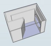
the idea of a hybrid tapped horn is very interesting. One working example is the Cubo 15" posted on Freespeakerplans forum.
Cubo 15
This has a bandpass chamber, feeding a tapped horn.
Probably not what you are thinking about at all, but intriguing!")
Hi Patrick
the idea of a hybrid tapped horn is very interesting. One working example is the Cubo 15" posted on Freespeakerplans forum.
Cubo 15
This has a bandpass chamber, feeding a tapped horn.
Probably not what you are thinking about at all, but intriguing!
Hi Patrick
the idea of a hybrid tapped horn is very interesting. One working example is the Cubo 15" posted on Freespeakerplans forum.
Cubo 15
This has a bandpass chamber, feeding a tapped horn.
Probably not what you are thinking about at all, but intriguing!
Just to make something clearer...
The Cubo is something between a tapped horn and an 6th order series tuned bandpass alignment, just a TH with a big rear chamber instead of the first segment of the horn, or a 6th order BPH with the rear vent feeding the "hornloaded" front chamber.
I guess patrick was thinking of a design the other way round, respective the mouth of a TH is feeding a chamber which is vented via a port to the outside, or a bose style tripple chamber bandpass with a tapped horn instead of the two internal (paralell tuned 6th bp) chambers.
Isn't it?
How about a front loaded horn with passive radiators on the chamber sides.Is this loony?
Does anyone know if it's possible (or reasonable) to combine a bandpass with a tapped horn? In other words, a subwoofer with two chambers. The first chamber is a tapped horn. The second chamber is fed by the tapped horn, and has a port. The mass of air in the second chamber is an acoustic low pass, and reduces distortion. It also resonates, and that reduces excursion. (A fourth excursion minimum.)
Here's my idea:
- A tapped horn has relatively wide bandwidth, high efficiency, and three excursion minimums.
- A triple reflex bandpass box has narrow bandwidth, high efficiency, and three excursion minimums.
- If one combined both, you could potentially get a fourth excursion minimum, and a reduction in distortion via the acoustic filtering of a bandpass enclosure.
Is it possible? I'm not exactly sure what you are proposing but it sounds like a tapped horn with an additional resonator attached to the mouth. It sounds very possible.
Is is reasonable? (Or even a good idea?) I don't think so. It would definitely have to be modeled accurately in akabak, since usually tapped horns are quite fussy about the distance from the driver's mouth side tap to the mouth, which will change dramatically if you add another resonator to the mouth of the horn.
Technically though, you can string together any number of chambers in a bass enclosure, and those chambers can be any number of different shapes. All you have to do is make sure the total volume is large enough to support the low frequencies and the impedance peaks are spaced sufficiently to achieve the bandwidth you desire. The problem with this is that only akabak will be able to model such a creation and it probably won't have any advantage over a simple, well designed front loaded or tapped horn of the same total volume.
You really don't need any more impedance peaks than a front loaded or tapped horn can provide anyway. Both of them have enough to achieve 3 octaves of bandwidth.
To recap, the number and spacing of the impedance peaks determine the bandwidth. The total enclosure volume determines the efficiency of acoustic loading. You can make a complex enclosure with lots of weird chambers if you want to but it probably will not outperform a well designed front loaded or tapped horn of similar size.
Last edited:
Bad enough to have any resonances fall in the pass band, let alone to seek to traffic in them. Shame! Any benefit is meretricious*, not musical.
If that's your idea of making a loud loudspeaker, make a Karlson.
Other than that, an interesting intellectual doodle.
*1.
a. Attracting attention in a vulgar manner: meretricious ornamentation. See Synonyms at gaudy1.
b. Plausible but false or insincere; specious: a meretricious argument.
2. Of or relating to prostitutes or prostitution: meretricious relationships.
Last edited:
"The Cubo is a clone of the EV SH18 (and Turbo did one as well?)
Another kick bass speaker. Not everything that shows the back of the speaker in the mouth is a TH. "
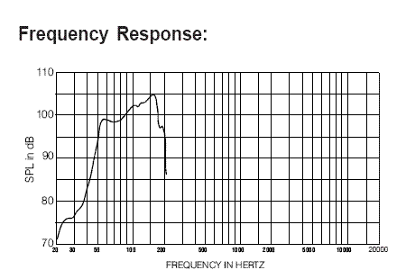
Kick is right, 6dB~7dB peaking in the 160hz region.
How about a TH?
A 4015LF or 15TBX100 also work well.
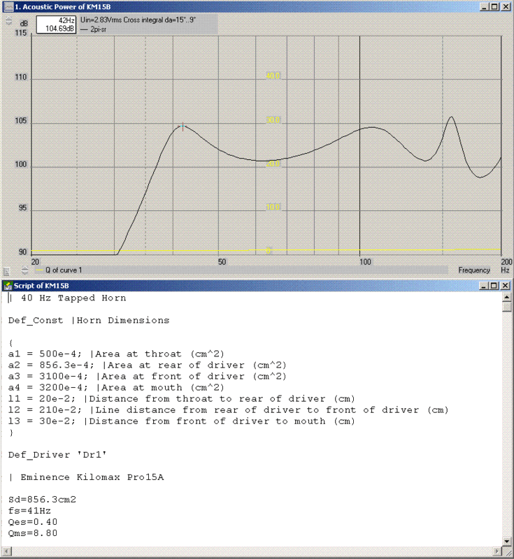
What do you need? 98dB at 55hz, or 104dB+ at 42hz?
Another kick bass speaker. Not everything that shows the back of the speaker in the mouth is a TH. "
Kick is right, 6dB~7dB peaking in the 160hz region.
How about a TH?
A 4015LF or 15TBX100 also work well.
What do you need? 98dB at 55hz, or 104dB+ at 42hz?
Gregg's circular opening simplified approximation of a Karlson - about two cubic foot total air space (anyone here game to make a competing Karlson model?)
An externally hosted image should be here but it was not working when we last tested it.
Bad enough to have any resonances fall in the pass band, let alone to seek to traffic in them. Shame! Any benefit is meretricious*, not musical.
Sometimes, it's hard to come up with a place to use a word like meretricious, but you've pulled it off nicely!
...
So you want to add a bandpass filter to a tapped horn? I wonder if this is going to degrade time domain performance too much. One of the challenges with tapped horns is that they can tend to ring. Does this become worse if you add a port? If you build it then consider looking at what happens to group delay.
The most prominent difference between the Cubo and those designs is that the horn mouth is considerably smaller. This results in more even distribution of efficiency over the entire pass band.The Cudo is a clone of the EV SH18 (and Turbo did one as well?)
Another kick bass speaker
The Cubo is actually an offspring of a multiple configurable horn. The pictures dotted lines show where the driver could be mounted. The rear loaded band pass horn was considerably louder below 120 Hz then the front loaded horn of equal dimensions. It was optimised from there.
The front loaded horn is pretty much equal to the D-horn.
The loud kick is there but it's hardly a kick bin (and/or low mid).
Best regards Johan
Attachments
The most prominent difference between the Cubo and those designs is that the horn mouth is considerably smaller. This results in more even distribution of efficiency over the entire pass band.
The Cubo is actually an offspring of a multiple configurable horn. The pictures dotted lines show where the driver could be mounted. The rear loaded band pass horn was considerably louder below 120 Hz then the front loaded horn of equal dimensions. It was optimised from there.
The front loaded horn is pretty much equal to the D-horn.
The loud kick is there but it's hardly a kick bin (and/or low mid).
Best regards Johan
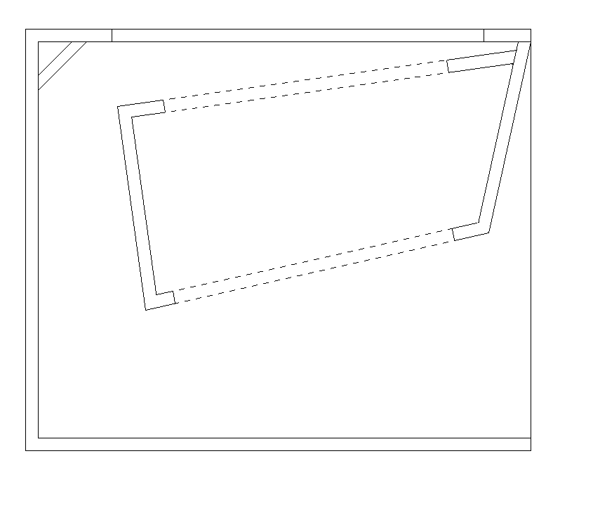
Looks like a tapped horn with a throat chamber.
An externally hosted image should be here but it was not working when we last tested it.
An externally hosted image should be here but it was not working when we last tested it.
It's a tapped horn. You should be able to simulate it fairly well in Hornresp. Removing all the braces makes its shape clearer.
thanks doll, i wrote in akabak before i posted but i didn't sure that was correct. don i feel a bit hate in the design so that i change to a new one . thanks again don.
Attachments
- Status
- This old topic is closed. If you want to reopen this topic, contact a moderator using the "Report Post" button.
- Home
- Loudspeakers
- Subwoofers
- Bandpass + Tapped Horn