Here's the plans for a 15hz tapped horn that I'm building.
There are a number of plans on the forums for tapped horns, but this is a bit different. Here's why:
All in all, this tapped horn may be a good candidate for your home theater.
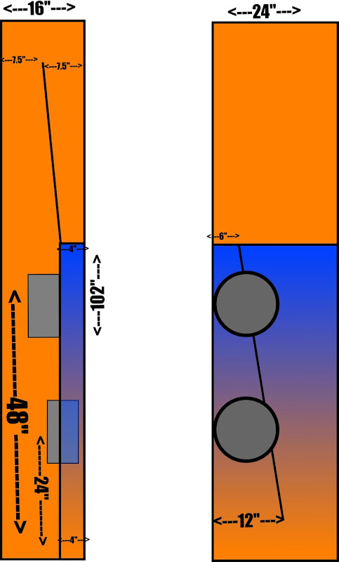
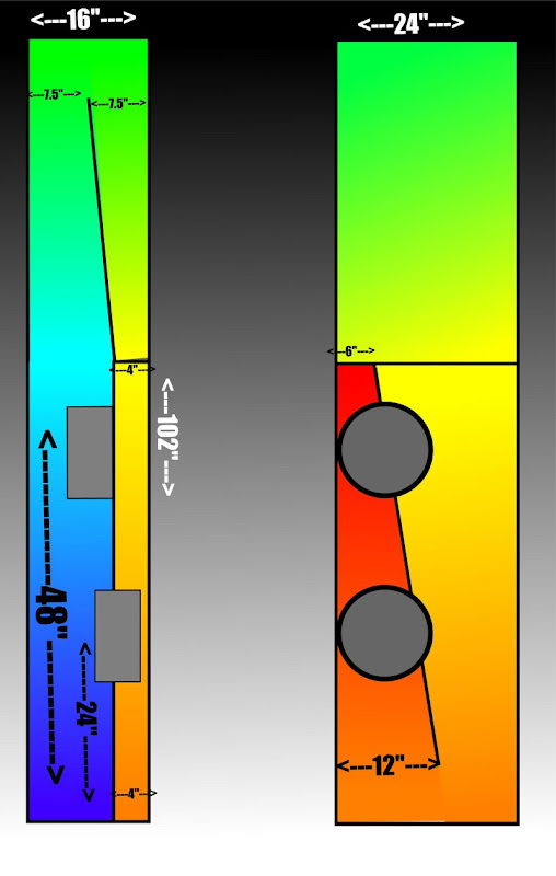
I spent most of the time optimizing the volumes in Akabak, so the plans themselves are kind of rough. (I'll post the Akabak sims later.) The outside dimensions are 102" tall, 24" wide, and 16" deep. That's twenty three cubic feet(!)
Sims coming soon...
There are a number of plans on the forums for tapped horns, but this is a bit different. Here's why:
- I've built a few tapped horns, and I've found that the use of multiple drivers smooths out the response. This one uses two drivers, but it's spaced as if there's three. This offers the benefits of multiple drivers, while maintaining an easy load on the amp.
- Conventional horns and bandpass subs roll off the highs. The low-pass filter effect of the horn reduces 2nd and 3rd harmonic distortion. Tapped horns don't really work the same way, particularly if the woofers are mounted close to the mouth. In my experiments, I've found that cheap drivers can sound good in a conventional front loaded horn, but tapped horns like a driver with lots of xmax and low distortion. To this end, I've selected a pair of twelves with 24mm of xmax, and shorting rings.
- To further reduce distortion, I'm using push-pull mounting to lower the 2nd harmonic.
- I'm using an extraordinarily large box to raise efficiency and smooth out response.
All in all, this tapped horn may be a good candidate for your home theater.
I spent most of the time optimizing the volumes in Akabak, so the plans themselves are kind of rough. (I'll post the Akabak sims later.) The outside dimensions are 102" tall, 24" wide, and 16" deep. That's twenty three cubic feet(!)
Sims coming soon...
Whatever you do, don't ... don't ... don't believe the hype. Build it and see! =]

I've been thinking of a similar project. A horn with a replaceable driver panel that could have up to four drivers mounted so I could test combining and spacing. After doing some sims I'm not convinced that there is much merit in it, but I'd love to see how this turns out!
How low can it go?!?
I've been thinking of a similar project. A horn with a replaceable driver panel that could have up to four drivers mounted so I could test combining and spacing. After doing some sims I'm not convinced that there is much merit in it, but I'd love to see how this turns out!
How low can it go?!?
Last edited:
Where is the mouth, at the bottom (24 x 12) ?
You can put it anywhere on the bottom; it's 1558 sq cm. (241 square inches.) I haven't decided where to put it yet, because I haven't decided if I'm going to mount it from my wall, or simply put it in the corner.
Here's the Akabak model. Note that this is a "true" dual driver model. Hornresp can't do this - it models multiple woofers as if they're radiating from the same point in space. The use of multiple woofers can extend the bandwidth of a tapped horn, and you need Akabak to model that.
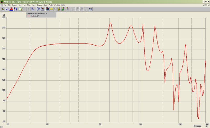 Here's the predicted response. This is with 49 volts. It basically has a bandwidth of three octaves, from 16hz to 128hz. That top octave is a bit rough; I intend to roll it off at 80hz.
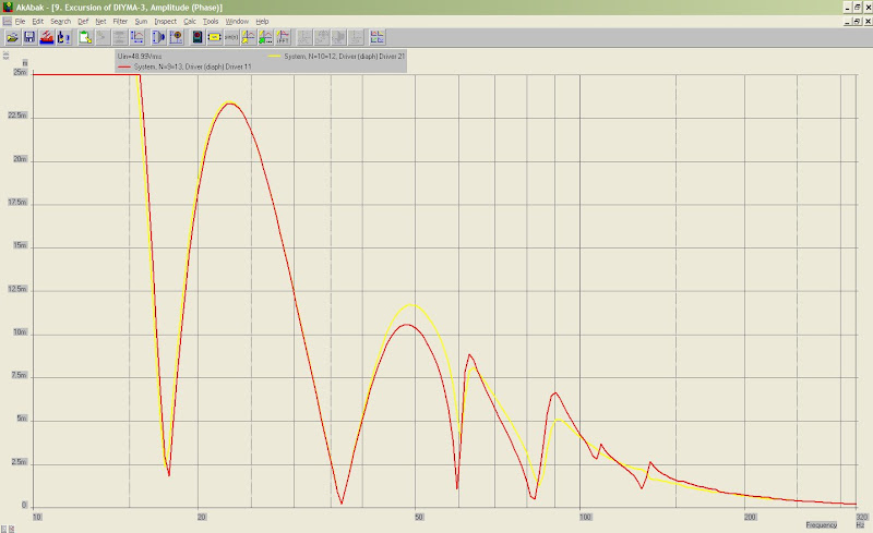 And the predicted excursion. The driver has 25mm of excursion - we can get down to 15hz or so at house-shaking levels.
System 'S1'
|DATA EXPORTED FROM HORNRESP - RESONANCES NOT MASKED
|COMMENT: th-mini clone, xara file is on other pc, 5/10/09. This one w/MCM 55-2421x2
|================================================= ================================================== =====
|REQUIRED AKABAK SETTINGS:
|File > Preferences > Physical system constants:
|Sound velocity c = 344m/s
|Medium density rho = 1.205kg/m3
|Sum > Acoustic power:
|Frequency range = 10Hz to 20kHz
|Points = 533
|Input voltage = 31.62V rms
|Integration = 2Pi-sr
|Integration steps = 1 degree ... 1 degree
|Integration method = Cross
|================================================= ================================================== =====
Def_Const |Hornresp Input Parameter Values
{
|Length, area and volume values converted to metres, square metres and cubic metres:
Rg = 0.01e-0; |Amplifier output resistance (ohms)
S1 = 155.00e-4; |Horn segment 1 throat area (sq cm)
S2 = 225.25e-4; |Horn segment 1 mouth area and horn segment 2 throat area (sq cm)
S3 = 296.70e-4; |Horn segment 2 mouth area and horn segment 3 throat area (sq cm)
S4 = 593.40e-4; |Horn segment 3 mouth area and horn segment 4 throat area (sq cm)
S5 = 1558.00e-4; |Horn segment 4 mouth area and horn segment 5 throat area (sq cm)
S6 = 1558.10e-4; |Horn segment 5 mouth area and horn segment 6 throat area (sq cm)
S7 = 1558.20e-4; |Horn segment 6 mouth area (sq cm)
L12 = 30.20e-2; |Horn segment 1 axial length (cm)
L23 = 60.80e-2; |Horn segment 2 axial length (cm)
L34 = 228.6e-2; |Horn segment 3 axial length (cm)
L45 = 274.32e-2; |Horn segment 4 axial length (cm)
L56 = 60.80e-2; |Horn segment 5 axial length (cm)
L67 = 60.80e-2; |Horn segment 6 axial length (cm)
|Parameter Conversions:
Sd = 982.00e-4; |Total diaphragm area for 2 parallel drivers (sq cm)
}
|================================================= ================================================== =====
|Network node numbers for this tapped horn system:
|0-Voltage-1-Resistance-2----------
| x x
| --Driver1------ ---------------------------
| x -Driver2-------------- x
| x x x x
| 8-Segment-9-Segment-10-Segment-11-Segment-12-Segment-13-Segment-14-Radiator
|================================================= ================================================== =====
Def_Driver 'Diyma12'
Sd=491.00cm2
Bl=18.05Tm
Cms=1.21E-04m/N
Rms=8.57Ns/m
fs=27.0000Hz |Mmd = 73.86g not recognised by AkAbak, fs calculated and used instead
Le=2.03mH
Re=3.80ohm
ExpoLe=1
System 'System'
Resistor 'Amplifier Rg'
Node=1=2
R={Rg}
Driver Def='Diyma12''Driver 11'
Node=2=0=9=13
Driver Def='Diyma12''Driver 21'
Node=2=0=10=12
Waveguide 'Horn segment 1'
Node=8=9
STh={S1}
SMo={S2}
Len={L12}
Conical
Waveguide 'Horn segment 2'
Node=9=10
STh={S2}
SMo={S3}
Len={L23}
Conical
Waveguide 'Horn segment 3'
Node=10=11
STh={S3}
SMo={S4}
Len={L34}
Conical
Waveguide 'Horn segment 4'
Node=11=12
STh={S4}
SMo={S5}
Len={L45}
Conical
Waveguide 'Horn segment 5'
Node=12=13
STh={S5}
SMo={S6}
Len={L56}
Conical
Waveguide 'Horn segment 6'
Node=13=14
STh={S6}
SMo={S7}
Len={L67}
Conical
Radiator 'Horn mouth'
Node=14
SD={S7}
That is head-explodingly ridiculous.
Have you considered charging people for the removal of kidney stones? Just give 'em some earplugs and put on your DVD of "Earthquake"...
Or that version of "Clubbed to Death" by Rob Dougan with all the ultra low frequency stuff...
Most cones are Ok if the pressure is applied all over the cone. For example, most speakers will stand being in a vented box, where, at the tuning frequency, the cone excursion is very very small, yet output is relatively large. The answer seems to be "don't worry about it".
If you have that much space, why not just make a sealed box? Not low enough for ya... add putty to the dust cap.
I thought sealed boxes best addressed truly challenging issues of distortion, flat response (down to resonance where some bump-up can't be bad if low enough), and cones flapping in the wind below resonance.
Am I biased towards sealed boxes because (1) there's no reason to do the math with a sealed box and anyway (2) I can't use those TS tools on my Mac?
Sure, lets go sealed.
Accounting for only Xmax of each the TH would produce 120dB at 17Hz according to AkAbak.
Put that into this calculator.
Piston Excursion calculator
Unless I typed something wrong you would need 11 drivers to keep up.
Accounting for only Xmax of each the TH would produce 120dB at 17Hz according to AkAbak.
Put that into this calculator.
Piston Excursion calculator
Unless I typed something wrong you would need 11 drivers to keep up.
Unless I typed something wrong you would need 11 drivers to keep up.
And THAT'S why sealed is not being considered
Sure, lets go sealed.
Accounting for only Xmax of each the TH would produce 120dB at 17Hz according to AkAbak.
Put that into this calculator.
Piston Excursion calculator
Unless I typed something wrong you would need 11 drivers to keep up.
Unless my understanding of the laws of physics are faulty or we are not talking apples-to-apples as the baseline, you'll need to explain that to me.
Please.
Last edited:
- Status
- This old topic is closed. If you want to reopen this topic, contact a moderator using the "Report Post" button.
- Home
- Loudspeakers
- Subwoofers
- Night of The Living Bassheads