Hi
I am currently busy building the woofer part of my 5.1 main system. This system is also used when playing music.
I did not want to make things too expensive so. I sourced two unknown brand 12" woofers. They did not have ANY parameters of any sorts basically the only data i have is 8ohm 350W max.
I decided i wanted to use both in one enclosure because of the lower wattage rating.
Because i didn't have any info i opt for a sealed enclosure.
The size is 440 x 440 x 840 mm
Here is my enclosure build:
I then went onto measuring the frequency responce. I do not have expensive measuring equipment so i basically used a microphone on my pc input and room EQ.
this was my first measurement with speakers and no filtering:
So i went into some reading , and according to these measurements i designed a linkwitz transform. AFter some testing and testing and changes I stil found a dip at 25hz and a large peak at 68Hz. So i added a 2 channel parametric filter. This is a measurement of these two filters:
These filters was based on Rod Elliot's pages.
After these filters this is what i measured with the microphone:
I am VERY happy with the improvement. Currently I'm using one 100W amplifier I built as a previous project on these two speakers. But The next step is the main amplifier. I am designing a 300W amplifier which should be AMPLE for my needs.
Any input or pointers would be appreciated.")
I am currently busy building the woofer part of my 5.1 main system. This system is also used when playing music.
I did not want to make things too expensive so. I sourced two unknown brand 12" woofers. They did not have ANY parameters of any sorts basically the only data i have is 8ohm 350W max.
I decided i wanted to use both in one enclosure because of the lower wattage rating.
Because i didn't have any info i opt for a sealed enclosure.
The size is 440 x 440 x 840 mm
Here is my enclosure build:
An externally hosted image should be here but it was not working when we last tested it.
An externally hosted image should be here but it was not working when we last tested it.
An externally hosted image should be here but it was not working when we last tested it.
An externally hosted image should be here but it was not working when we last tested it.
An externally hosted image should be here but it was not working when we last tested it.
An externally hosted image should be here but it was not working when we last tested it.
An externally hosted image should be here but it was not working when we last tested it.
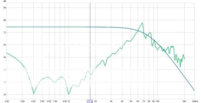
I then went onto measuring the frequency responce. I do not have expensive measuring equipment so i basically used a microphone on my pc input and room EQ.
this was my first measurement with speakers and no filtering:
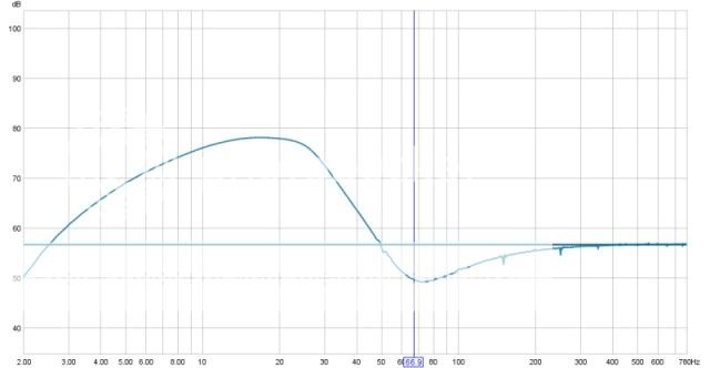
So i went into some reading , and according to these measurements i designed a linkwitz transform. AFter some testing and testing and changes I stil found a dip at 25hz and a large peak at 68Hz. So i added a 2 channel parametric filter. This is a measurement of these two filters:
An externally hosted image should be here but it was not working when we last tested it.
These filters was based on Rod Elliot's pages.
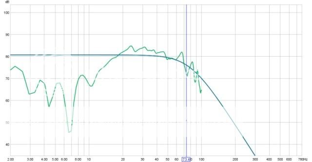
After these filters this is what i measured with the microphone:
I am VERY happy with the improvement. Currently I'm using one 100W amplifier I built as a previous project on these two speakers. But The next step is the main amplifier. I am designing a 300W amplifier which should be AMPLE for my needs.
Any input or pointers would be appreciated.
I am currently designing a pc board and also schematic.
I am using multisim and ultiboard from the national website. Planning on posting schematic and pcb design if someone else wants to use it when i am done.
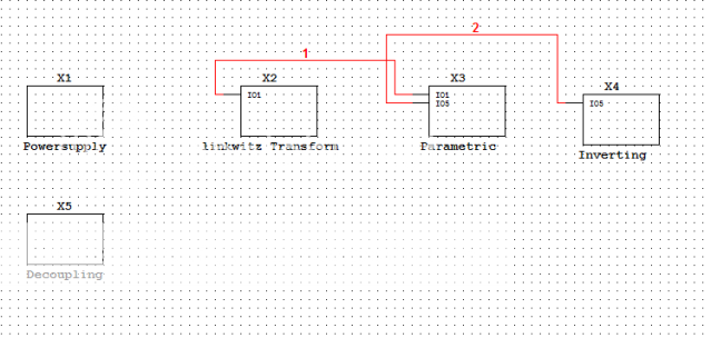
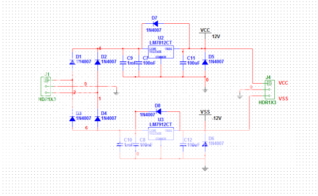
Schematic parts:
1) +-12v powersupply (using 78012 and 7912)
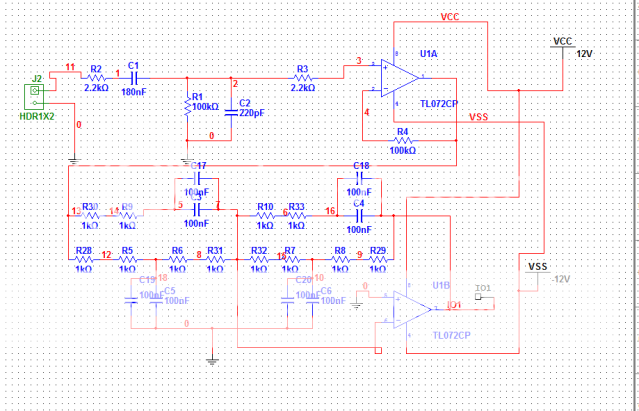
2) linkwitz transform circuit closely resembling circuit diagram on Rod elliot pages (the capacitor and resistor sizes will be different depending on driver and enclosure used)
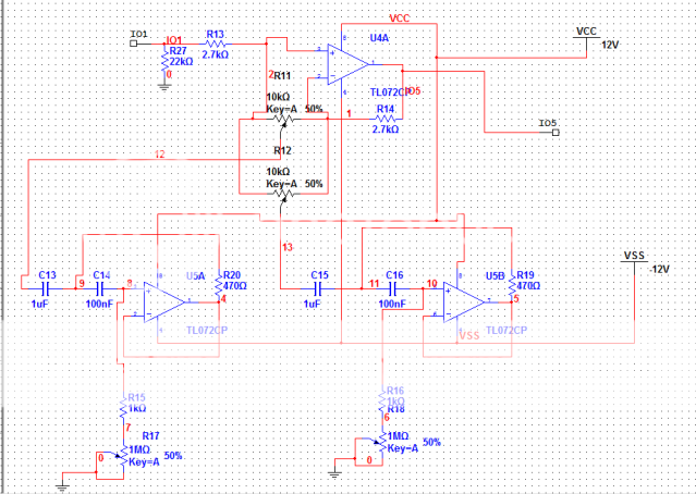
3) 2 channel parametric ( is set it to 25 hz and 8 hz , I had a 3db dip at 25hz and a large peak at 68hz and i used this to flatten them both but the frequency can be set according to your taste/needs
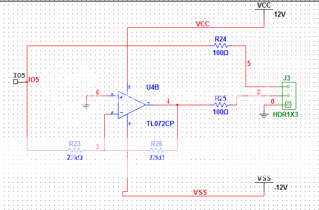
4) opamp circuit to get non inverting and inverting output , i need a balanced output for the amps i am going to bridge.
I am using multisim and ultiboard from the national website. Planning on posting schematic and pcb design if someone else wants to use it when i am done.
Schematic parts:
1) +-12v powersupply (using 78012 and 7912)
2) linkwitz transform circuit closely resembling circuit diagram on Rod elliot pages (the capacitor and resistor sizes will be different depending on driver and enclosure used)
3) 2 channel parametric ( is set it to 25 hz and 8 hz , I had a 3db dip at 25hz and a large peak at 68hz and i used this to flatten them both but the frequency can be set according to your taste/needs
4) opamp circuit to get non inverting and inverting output , i need a balanced output for the amps i am going to bridge.
Hi guys
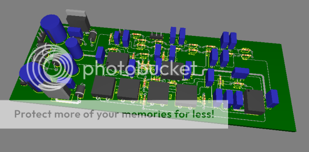
I am currently busy with a little pc board for the circuit.
here is the current progress.
NOTE: NOT ALL the components have correct sizes yet for example all the linkwitz transform parts are currently just 1k and 100nf i'll fix this later. The powersupply and final inverter circuit(to get balanced output) components are correct.
I am still checking to see if i didn't make any errors somewhere , so if you see any please tell me!
RapidShare: 1-CLICK Web hosting - Easy Filehosting
There you have it
for anyone that is interested.
I found one error in the schematic with 2 diodes i had wrong way round in the power supply part.
In the Rapidshare link is the Multisim and Ultiboard files and also the Gerbers.
If there is anyone out there that is interested in this board give me a shout. We can make a few together and save the cost , or I already did and I can ship you some at cost.
Certainly looks nice and great job on the filter, i want to make a similar one too but i'll have to finish the sub enclosure first, and i have exams now so that'll be in a couple months.
If you decide you want a better enclosure later on, you can measure the speakers' T/S parameters with little more than your soundcard, amplifier and a resistor. Check out audioTester!
If you decide you want a better enclosure later on, you can measure the speakers' T/S parameters with little more than your soundcard, amplifier and a resistor. Check out audioTester!
yeah , getting decent measurement equipment would be cool.
I did it really bad, I used a microphone in front of speaker to decide on values for my transform circuit. those measurements you see is microphone measurements 10cm in front of speaker. I am very happy with the result and difference between no transform and circuit.
much less "peaky"
I did it really bad, I used a microphone in front of speaker to decide on values for my transform circuit. those measurements you see is microphone measurements 10cm in front of speaker. I am very happy with the result and difference between no transform and circuit.
much less "peaky"
Well if you weren't clipping the mike preamp measurements can't be THAT bad, i have a self-built mic with an electret capsule recovered from a Toshiba Portege 4010 laptop motherboard, and let me tell you that it has INCREDIBLE response.
Not once have my friends told me to turn the bass down when i was listening to music while talking with them on Skype. I just need to find someone with a calibrated reference mic so i can calibrate mine for SPL measurements. I haven't tried measuring FR with it yet but it makes excellent recordings. Can't beat that for free.
Still do check out that piece of software when you have some time, it can do lots of stuff and it's free for 30 days with all functions available. I use a plain old Audigy soundcard and a vintage 25 wpc amp to measure and test speakers, and after calibration (you just need to do a line out -> amp -> line in loop) the results are quite accurate. Probably a bit short of a Woofer Tester 3 but i have built several boxes based on the measurements i made, including a bandpass sub, and they all sound great.
Not once have my friends told me to turn the bass down when i was listening to music while talking with them on Skype.
I just need to find someone with a calibrated reference mic so i can calibrate mine for SPL measurements. I haven't tried measuring FR with it yet but it makes excellent recordings. Can't beat that for free. Still do check out that piece of software when you have some time, it can do lots of stuff and it's free for 30 days with all functions available. I use a plain old Audigy soundcard and a vintage 25 wpc amp to measure and test speakers, and after calibration (you just need to do a line out -> amp -> line in loop) the results are quite accurate. Probably a bit short of a Woofer Tester 3 but i have built several boxes based on the measurements i made, including a bandpass sub, and they all sound great.
Last edited:
Yeah , I was also worried about clipping while doing test.
I did my frequency responce test at various volumes. Differences in measurements was very very small (except for the ovious spl level and the obvious HIGH level setting that had clipping) in the end I settled for a very low level anyway.
That is why i designed the cuircuit in the end , because it can be used with any speaker and sealed enclosure. you just vary the linkwitz(cap and resistor) parts for various speakers and enclosures.
I am very impressed with the results! To think you could, after tweaking, get such response from 'no name' woofers is incredible. However, if I read this correctly the measurements were made close to the speaker- what about room loading? Things look pretty flat right now between 20-50hz. What is it like at your listening position?
My listening position is on the couch. Sub Drivers are left about 2m forward and about 1meter left.
I do realize that a lot of the peaks would be due to the room.
IN the end my goals where to get things as good as I could get them. Knowing it would never be perfect. one thing I am sure of is that it sounds much better with the circuit than without it.
without the circuit it was VERY loud at certain low notes and softer at other as can clearly be seen by testing in first test graph. When listening to music lower notes had clear loudness difference depending on frequency.
with circuit the same song sound much better with all lower notes sound "the same"
Frequency sweep also sound much better with filter circuit.
I do realize that with more expensive woofers i would need MUCH less amplification on lower frequencies ,but at this stage i believe that all woofers in a sealed enclosure can do with a filter like this.
At this stage I am very busy with the amplifier....
- Status
- This old topic is closed. If you want to reopen this topic, contact a moderator using the "Report Post" button.
- Home
- Loudspeakers
- Subwoofers
- My first build