In tapped horn theory, is there some requirement that the rear of the driver sits at or near the horn mouth, a la jbell's tapped horn?
(http://www.diyaudio.com/forums/subwoofers/127908-jbells-set-four-tapped-horns.html)
Also, I'm following lilmike's tutorial on tapped horns at Simple Tapped Horn Tutorial using Hornresp - AVS Forum and in reference to jbell's design, I believe the L23 segment is the entire distance between the middle of the cone on the front side, and the middle of the magnet on the back side, irrespective of the number of folds and such in between - is that correct?
Along those lines, can anyone tell me the practical effect of having the back of the driver recombine very close to the front, i.e. a shorter L23 and a much longer L34?
And, are there any ill effects I should know about with regard to having multiple folds and such?
THX!
In tapped horn theory there's the requirement that the rear of the driver sits behind the horn mouth. It doesn't have to be close, i.e. L34 can be made very long if desired.
The physical mounting of the driver is relatively meaningless, the driver can be reversed mounted if desired, which results ussually in small changes to S2, S3, etc. It's effects are often ignored in simulations. Measurements showed an 1 dB difference between standard or reversed mount in several designs (a little less on that frequency a bit more there kinda thing).
Your believe about L23 is correct. Mind you that HR offers the option of dividing "L23" into 2 segments, meaning L23 starts at one side and L34 ends at the other side of the driver.
I did some sims in the past regarding your idea of keeping L23 small, IIRC it was difficult to get anything else but a peaky response, most tapped horns build these days seem to have the driver close to the mouth. With L34 up to 55 cm I aquired some good results (L23 was more then 55 cm in those cases).
Bends have multiple effects, amongst are the increased horn path length with regards to the axial measured length and the "termination" of higher frequencies, i.e ; Lots of bends mean your not likely going to get 120 Hz plus out of the tapped horn whilst still sounding "good".
Best regards Johan
Last edited:
Thanks for the reply. My questions stem from an idea to build subs where the driver is mounted in the top of a vertical cabinet, which is perhaps 48 inches tall and 24 inches wide. It would be a single 15 or single 18 inch driver. I would put a plexiglass or lexan window at the front of the driver chamber, and maybe even a neon light or small rope lights in the driver chamber for illumination of the cone. I would design it in such a way that the L23 is very short because the front and back of the driver would combine very close, like with one fold between the front and back, then multiple folds and a long path length on L34 between the back of the driver and the horn mouth.
If there are big swings in the response curve, that may be rectified by the use of another tuned circuit along with the driver (but that's a rather advanced topic that I'm not knowledgeable on - yet). I will start modeling and post back to this thread if I come up with anything nice.
If there are big swings in the response curve, that may be rectified by the use of another tuned circuit along with the driver (but that's a rather advanced topic that I'm not knowledgeable on - yet). I will start modeling and post back to this thread if I come up with anything nice.
... I would design it in such a way that the L23 is very short because the front and back of the driver would combine very close, like with one fold between the front and back, then multiple folds and a long path length on L34 between the back of the driver and the horn mouth.
Take a look at the clones of Tom Danley's TH-SPUD tapped horn. The L34 length (driver to mouth) is quite long - the full width of the cabinet. However, the L23 length is still much longer than L34. I supect you'll have to lay out your folds in such a way that you get your desired driver placement but still have a long L23.
That's kinda like saying the same thing in the same sentence twiceI would design it in such a way that the L23 is very short because the front and back of the driver would combine very close
")
I really think it's a hard way of doing it. You're creating a big spike just before the low cut off and little efficiency above that, unless you're making it like a 65 Hz plus cabinet, with a large throat chamber and large mouth, which you probably aren't.
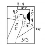
There are lots of folding scheme's to choose from, that would make it appear that L23 is short while that's not necessarly so. I've attached a quick sketch (it's up to scale but that's it) as how the image struck me, might be way off though.
Best regards Johan
Attachments
That's kinda like saying the same thing in the same sentence twice
Yes, sometimes I am redundant like that
I've attached a quick sketch (it's up to scale but that's it) as how the image struck me, might be way off though.
Thanks for the sketch, the driver placement is correct but I would have the cone facing forward (toward the glass). When I finish modeling, I will draw something and post it. I'm still having a hard time understanding how I can model the folds though - how can I know to what degree the folds will affect the upper corner response if Hornresp does not take them into consideration? Are there any "rules of thumb" I can use?
I don't think people are factoring in the volume of the driver when they model tapped horns. I'm thinking of doing a TH for my truck. I had the original size of the mouth at 1,651.61cm^2 (16" x 16"). If I build it, I am going to use a 1,961.29cm^2 (19" x 16") mouth to account for the 0.5ft^3 volume of the driver and expect the 16in^2 frequency response.The physical mounting of the driver is relatively meaningless, the driver can be reversed mounted if desired, which results ussually in small changes to S2, S3, etc. It's effects are often ignored in simulations. Measurements showed an 1 dB difference between standard or reversed mount in several designs (a little less on that frequency a bit more there kinda thing).
Best regards Johan
The best rule of thumb is to ignore the effects of the folds on the upper corner response. The folds will only affect frequencies well above the upper corner. If you think about it, the folds form a series of shorter pipes, each of which will resonate at a much higher frequency than the overall pipe length. Just make sure you don't alter the calculated pipe length when you make the folds. Draw it out to scale on a piece of graph paper and measure down the mid-line of each section and through the bends to double check.
That makes perfect sense, thanks. Now one other thing I'm having a hard time understanding, as I go to model this horn, is the relationship of the segments. In lilmike's tutorial he gives the following illustration:
http://lh6.ggpht.com/_WXjTASetbPo/Sz-2v-KLvnI/AAAAAAAAAFU/kLFcYVflWfI/annotated tapped horn.jpg
(if that does not work, it's the same illustration at the top of post #2 in his thread: Simple Tapped Horn Tutorial using Hornresp - AVS Forum)
What I am not understanding is the relationship between S3 and the driver - he seems to locate S3 in the middle of the driver. But is there any reason S3 could not be modeled back a bit (i.e. just to the right of the driver)? I'm just trying to understand how the segments will relate to my folds when I actually go to build this thing.
Also, I saw no mention of Vtc and Atc in lilmike's tutorial - are these parameters relevant to the model in the case of a tapped horn?
S3 is per definition right in front of the driver (in a 3 segment tapped horn). Ussually when designing a tapped horn the Vtc is kept to a minimum and like the influence of the driver position ignored in simulation.But is there any reason S3 could not be modeled back a bit (i.e. just to the right of the driver)?
Only when building hybrides between tapped horns en rear loaded band pass horns the Vtc-effect becomes significant.
Best regards Johan
Also, I saw no mention of Vtc and Atc in lilmike's tutorial - are these parameters relevant to the model in the case of a tapped horn?
Not too important in the simplest form. With a more complex design (multiple drivers, push-pull mounting, cases where Sd >> than S2, things like that) it may be necessary to include a throat chamber.
With the driver front mounted so the cone faces into the throat (typical), I model the hole through the baffle as a throat chamber, with ATC = the area of the hole, and Vtc = the area times the baffle thickness plus a little more for the volume of the cone. It does have an effect on the impulse response and phase, but very little effect on the frequency response of the enclosure.
Thanks littlemike, and everyone else for your contributions. An update on my design progress:
It quickly became evident that in order to have any hope of 25hz from a single cabinet, I'd need two drivers in series to split the voltage and thus splitting the excursion. The problem I found is that you lose a whopping 6db of overall performance by running 2 drivers in series, versus 2 in parallel (this is basic theory of course). But the prospect of being able to achieve a theoretical 150db from 2kw input (with drivers in parallel) sounded ohhh so nice! After modeling a few cheap drivers, then coming across the Lab 15 with an Xmax of 10.8, the choice was pretty clear: two of these in parallel, with something like 1.5 to 2kw of input power. It's worth noting that I modeled extensively with the JBL 2226H, which has a very complete spec sheet, but unfortunately it just doesn't get as low as the Lab 15, which is a purpose-built driver for subwoofers.
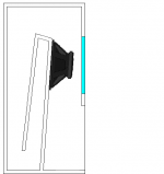
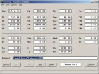
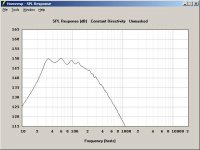
I'm including shots of hornresp with the parameters, and the response, along with a hornresp import file, and finally a sketch of my design, looking from the side. You will notice the driver filled in with solid black. Sorry in advance for the barely-legible text; the text indicates dimensions in centimeters. The external dimensions are 91.4 deep and 137 tall. The numbers given on the inside are the path lengths of each "fold segment". The drawing is not exactly to scale, as I simply duplicated something I drew up on paper yesterday. But as best I can tell, the fold segments and the segment areas are all proper in accordance with my hornresp parameters. Of course I will lay all of this out with construction paper or something before I do any cutting
Comments and criticisms are welcome. Also, closely related, has anyone measured the Lab 15 in any kind of horn design? A quick scan of the PSW Sound Reinforcement Forums (notably PSW Sound Reinforcement Forums: LAB Subwoofer => LAB15 basshorn design?) indicates that no one over there has built/measured a design with the Lab 15. I was rather curious to know how it'd do in PSW's "LAB sub box" which was designed for the Lab 12 driver.
thx!
It quickly became evident that in order to have any hope of 25hz from a single cabinet, I'd need two drivers in series to split the voltage and thus splitting the excursion. The problem I found is that you lose a whopping 6db of overall performance by running 2 drivers in series, versus 2 in parallel (this is basic theory of course). But the prospect of being able to achieve a theoretical 150db from 2kw input (with drivers in parallel) sounded ohhh so nice! After modeling a few cheap drivers, then coming across the Lab 15 with an Xmax of 10.8, the choice was pretty clear: two of these in parallel, with something like 1.5 to 2kw of input power. It's worth noting that I modeled extensively with the JBL 2226H, which has a very complete spec sheet, but unfortunately it just doesn't get as low as the Lab 15, which is a purpose-built driver for subwoofers.
I'm including shots of hornresp with the parameters, and the response, along with a hornresp import file, and finally a sketch of my design, looking from the side. You will notice the driver filled in with solid black. Sorry in advance for the barely-legible text; the text indicates dimensions in centimeters. The external dimensions are 91.4 deep and 137 tall. The numbers given on the inside are the path lengths of each "fold segment". The drawing is not exactly to scale, as I simply duplicated something I drew up on paper yesterday. But as best I can tell, the fold segments and the segment areas are all proper in accordance with my hornresp parameters. Of course I will lay all of this out with construction paper or something before I do any cutting
Comments and criticisms are welcome. Also, closely related, has anyone measured the Lab 15 in any kind of horn design? A quick scan of the PSW Sound Reinforcement Forums (notably PSW Sound Reinforcement Forums: LAB Subwoofer => LAB15 basshorn design?) indicates that no one over there has built/measured a design with the Lab 15. I was rather curious to know how it'd do in PSW's "LAB sub box" which was designed for the Lab 12 driver.
thx!
Attachments
tapped horn? or scoop?
The design is a tapped horn, however it's going to look a lot like a scoop, in that i'll have a plexiglass window in front of the drivers for the kiddies to look at.
I don't see the TH designation by the drivers???
I don't follow..
And .5pi? you always going to have this in a corner?
No; most of the time i'll be running them in 1pi, but I've done all of my modeling in 2pi just in case I should need to take them outdoors.
and at 130v, that's over 2kw, EACH driver....
ahh see, this is why I love you wonderful people
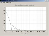
The 130v figure came from measured output of my Crown CE-2000 in a completely open (unloaded) configuration. As my mentor quickly pointed out, that's nowhere near accurate, both because it's open and because I ran it into clipping while taking the measurement. 88v is probably a more realistic "maximum of maximums" while under an inductive load with a pure sine-wave input.you should post your displacement chart.[/QUOTE]
See below, with input voltage adjusted to 88v. It's important to note that i'll use a DCX2496 with these, for a slight bit of limiting centered at 35hz, and a major amount between 20 and 30, probably with a band-pass configuration of 20hz - 200hz at 1/30th octave slopes.
Attachments
Thanks littlemike, and everyone else for your contributions. An update on my design progress:
It quickly became evident that in order to have any hope of 25hz from a single cabinet, I'd need two drivers in series to split the voltage and thus splitting the excursion. The problem I found is that you lose a whopping 6db of overall performance by running 2 drivers in series, versus 2 in parallel (this is basic theory of course). But the prospect of being able to achieve a theoretical 150db from 2kw input (with drivers in parallel) sounded ohhh so nice! After modeling a few cheap drivers, then coming across the Lab 15 with an Xmax of 10.8, the choice was pretty clear: two of these in parallel, with something like 1.5 to 2kw of input power. It's worth noting that I modeled extensively with the JBL 2226H, which has a very complete spec sheet, but unfortunately it just doesn't get as low as the Lab 15, which is a purpose-built driver for subwoofers.
I'm including shots of hornresp with the parameters, and the response, along with a hornresp import file, and finally a sketch of my design, looking from the side. You will notice the driver filled in with solid black. Sorry in advance for the barely-legible text; the text indicates dimensions in centimeters. The external dimensions are 91.4 deep and 137 tall. The numbers given on the inside are the path lengths of each "fold segment". The drawing is not exactly to scale, as I simply duplicated something I drew up on paper yesterday. But as best I can tell, the fold segments and the segment areas are all proper in accordance with my hornresp parameters. Of course I will lay all of this out with construction paper or something before I do any cutting
Comments and criticisms are welcome. Also, closely related, has anyone measured the Lab 15 in any kind of horn design? A quick scan of the PSW Sound Reinforcement Forums (notably PSW Sound Reinforcement Forums: LAB Subwoofer => LAB15 basshorn design?) indicates that no one over there has built/measured a design with the Lab 15. I was rather curious to know how it'd do in PSW's "LAB sub box" which was designed for the Lab 12 driver.
thx!
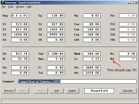
As jbell said - this is not a tapped horn.
Regardless of what you think you've modeled, those parameters are for a front-loaded horn with no back chamber and a set of three conical flares.
"Nd" will be "TH" in a tapped horn model.
Attachments
Last edited:
ahh thanks for pointing that out. It looks like I've got another half-day of modeling ahead of me in lieu of that mistake.
After I changed the driver arrangement to TH, I have a nosedive in the response at 140hz. Any recommendation as to what factors influence this so I can hopefully make it dive closer to 180 or 200?
After I changed the driver arrangement to TH, I have a nosedive in the response at 140hz. Any recommendation as to what factors influence this so I can hopefully make it dive closer to 180 or 200?
ahh thanks for pointing that out. It looks like I've got another half-day of modeling ahead of me in lieu of that mistake.
After I changed the driver arrangement to TH, I have a nosedive in the response at 140hz. Any recommendation as to what factors influence this so I can hopefully make it dive closer to 180 or 200?
I do not think you can model that in hornresp. I think the trick is to do the folding in such a way that that first large null/peak is cancelled by a standing wave in one of the folds. The danley tower of power has some tubes inside the long fold to remove that peak. The long "collaborative tapped horn" tread has some info on this. Somebody else may be able to find it in that really long thread.
/andreas
Actually, it's a Hornresp modeled rear loaded horn. His picture had me stumped too.As jbell said - this is not a tapped horn.
Regardless of what you think you've modeled, those parameters are for a front-loaded horn with no back chamber and a set of three conical flares.
AJHorn Manual
Last edited:
- Status
- This old topic is closed. If you want to reopen this topic, contact a moderator using the "Report Post" button.
- Home
- Loudspeakers
- Subwoofers
- Tapped horn theory