Yes, clamp a partial cover on, or use another cabinet (short the speaker out so it does not suck acoustical power) to block a portion of the mouth.
Reducing the mouth area will likely increase LF (slightly), and reduce upper response, which the cabinet seems to have plenty of.
If you keep the drive level the same, it will be easy to see if it helps or hurts performance.
I did a few quick runs to see if I could see any difference, and when I have about half(!) of the mouth covered I could see some small differences in the low end (maybe 3 db or something). Will try again today when I hopefully have more time.
Ditto. A WT3 can do it quickly for you. If you don't have a WT3, a resistor , a multimeter and a frequency generator (your PC and appropriate software) can be used to plot the impedance at various frequencies.
Yes, I know how I could measure it (dont have and dont even know what a WT3 is), but I am not sure I will go through the hassle to do it manually if the only idea behind that is see if there is a leak (because I am VERY sure there is none).
Is there another reason? Convince me
")
Yes, I know how I could measure it (dont have and dont even know what a WT3 is), but I am not sure I will go through the hassle to do it manually if the only idea behind that is see if there is a leak (because I am VERY sure there is none).
Is there another reason? Convince me
Comparing it with the HornResp prediction will let you know how close your built subwoofer is to the one that's modelled in HornResp (it is usually easier to get an accurate impedance response than an accurate frequency response).
See The Subwoofer DIY Page v1.1 - Projects : Using Impedance Graphs
3 dB would be half of the 6 dB (or so) LF droop that the cabinet presently shows.I did a few quick runs to see if I could see any difference, and when I have about half(!) of the mouth covered I could see some small differences in the low end (maybe 3 db or something). Will try again today when I hopefully have more time.
I'll be interested to see what happens to the upper response as well.
I would like to have an impedance tester in addition to my other test tools, but if you build decently, air leaks are not a problem, and frequency response is what we hear (unless hearing air leaks ;^).
3 dB would be half of the 6 dB (or so) LF droop that the cabinet presently shows.
I'll be interested to see what happens to the upper response as well.
I would like to have an impedance tester in addition to my other test tools, but if you build decently, air leaks are not a problem, and frequency response is what we hear (unless hearing air leaks ;^).
Well, it looks like more than 6db to me but... The "modification" certainly didnt cut the "problem" in half if I look at the graphs. Will measure again and post the graphs.
More measurements and impedance testing is on the wishlist now.
That would be really strange. JBL provides some good "silicone" string/tape to use for making sure it is sealed around the drivers. But of course, strange things can happen.tb46 said:E.g.: around the driver seals.
I now have the drivers and precut material for the second horn... Just need time now
Hi barco,
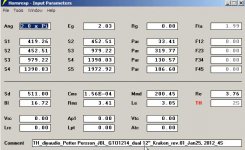
After looking at your SPL measurements I took another look at the Kraken 212 Hornresp model, and found that it could be improved (i.e.: made to fit the enclosure drawing better):
Regards,
After looking at your SPL measurements I took another look at the Kraken 212 Hornresp model, and found that it could be improved (i.e.: made to fit the enclosure drawing better):
Regards,
Attachments
Just can't get any of the 12" drivers I have on hand to look good in this cabinet. The closest I get to anything reasonable is with a Peerless 12" XLS sub and even that is not pretty(in sim). Then I figured I'd adjust the cabinet to suit my needs and have come up even more confused than before. Huge peak at 20 and 70Hz respectively and a 10dB drop between those two points if left alone in the kracken, adjusted well.... I'll post the sim of what I've come up with, see what you people think.
On a side note is there anyone willing to guide me on how to fold the horn line? I'd like to understand it more so it's not so mathematical yet still retains the integrity of the design.
On a side note is there anyone willing to guide me on how to fold the horn line? I'd like to understand it more so it's not so mathematical yet still retains the integrity of the design.
Hi barco,
After looking at your SPL measurements I took another look at the Kraken 212 Hornresp model, and found that it could be improved (i.e.: made to fit the enclosure drawing better):
Regards,
Sounds good, but since I only "stole" the design from Petter, I have no idea what the values in hornresp means
(well, I know they are dimensions).What have you done to it, have you decreased the output area?
Hi barco,
I redrew Petter's exact enclosure in AutoCAD, and remeasured the centerline using soho54's method for the corners. I did not change a thing about the enclosure, but went in the model from 3 horn sections to 4 horn sections.
S1 and S2 remain the same, as does L12. S4 becomes S5, and S3 becomes S4, L34 becomes L45. The former L23 is split into the new L23 and L34, and a new S3 is located in between the new S2 and S4. The location of the new S3 is adjusted to improve the fit between model and drawing.
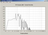
Even if you're not using Hornresp (yet) you can see at which frequency the response peaks, etc. are supposed to happen.....
Regards,
I redrew Petter's exact enclosure in AutoCAD, and remeasured the centerline using soho54's method for the corners. I did not change a thing about the enclosure, but went in the model from 3 horn sections to 4 horn sections.
S1 and S2 remain the same, as does L12. S4 becomes S5, and S3 becomes S4, L34 becomes L45. The former L23 is split into the new L23 and L34, and a new S3 is located in between the new S2 and S4. The location of the new S3 is adjusted to improve the fit between model and drawing.
Even if you're not using Hornresp (yet
) you can see at which frequency the response peaks, etc. are supposed to happen.....Regards,
Could you share the new design? So I understand what the difference is?Hi barco,
I redrew Petter's exact enclosure in AutoCAD, and remeasured the centerline using soho54's method for the corners. I did not change a thing about the enclosure, but went in the model from 3 horn sections to 4 horn sections.
S1 and S2 remain the same, as does L12. S4 becomes S5, and S3 becomes S4, L34 becomes L45. The former L23 is split into the new L23 and L34, and a new S3 is located in between the new S2 and S4. The location of the new S3 is adjusted to improve the fit between model and drawing.
Even if you're not using Hornresp (yet
Regards,
Hi barco,
Post #191: "...share the new design?..."
There is no new design, just an updated Hornesp model as shown in Post #187. For your information I'll attach the drawing from which I gathered the information. Again, the enclosure is not changed.
Regards,
Post #191: "...share the new design?..."
There is no new design, just an updated Hornesp model as shown in Post #187. For your information I'll attach the drawing from which I gathered the information. Again, the enclosure is not changed.
Regards,
Attachments
Hi barco,
Post #191: "...share the new design?..."
There is no new design, just an updated Hornesp model as shown in Post #187. For your information I'll attach the drawing from which I gathered the information. Again, the enclosure is not changed.
Regards,
Ahhhhh!! NOW I get it
(finally!)I thought you made some changes to how to build the horn, but it was the hornresp model that you changed to better reflect the measurements I have.
BTW, I have all the material pre-cut in the garage for the next horn so just to get started. Also got the miniDSP today so I guess I will see if I can play around with that and smooth the response of the horn a bit (I am sure I can).
Hi barco,
Two of those should be enough to "bring down the house".
Regards,
Actually, all I am looking for is to make my couch more balanced
So I have made some more measurements with open vs "closed" (not really closed, but almost half of the mouth closed).
There is differences, yes. But not that much (at least I dont think so).
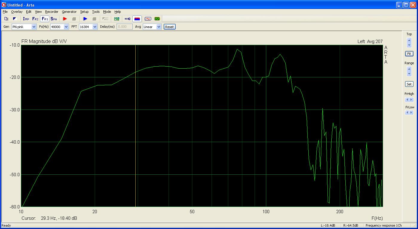
First, new measurement "same as before":
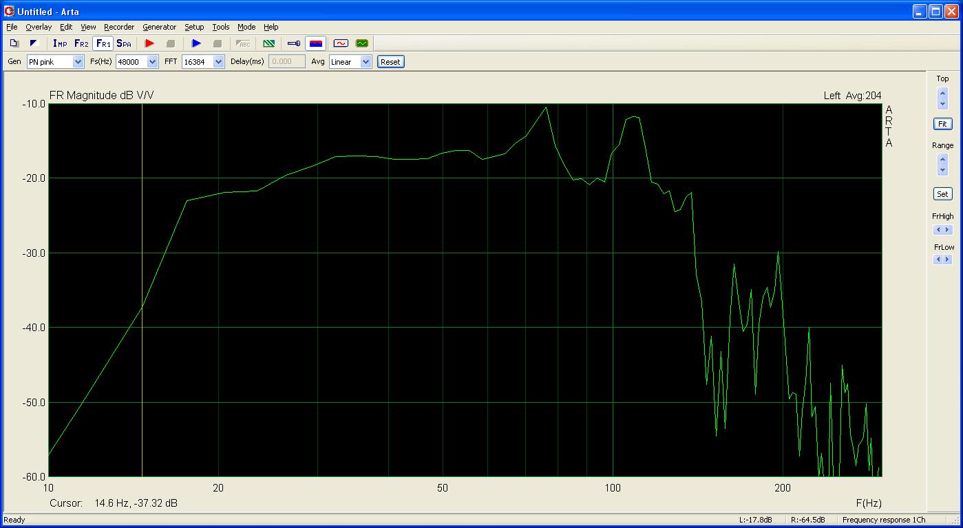
Second with "closed" mouth. Exactly the same setup with everything else (volume, mic placement etc):
There is differences, yes. But not that much (at least I dont think so).
First, new measurement "same as before":
An externally hosted image should be here but it was not working when we last tested it.
Second with "closed" mouth. Exactly the same setup with everything else (volume, mic placement etc):
An externally hosted image should be here but it was not working when we last tested it.
Hi barco,
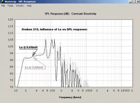
Your measurements in Post #196 both show a bump in the 30-40Hz region. I get a similar bump in Hornresp when I double the driver impedance (Le). As the driver impedance in the sub 100Hz range is usually not anything like the manufacturer's Le specification (which is normally measured @ 1kHz), a rising Le in this range may be the cause.
At the very low end, below 20Hz it looks like your system may have a low cut filter. Do you have any way of testing for this?
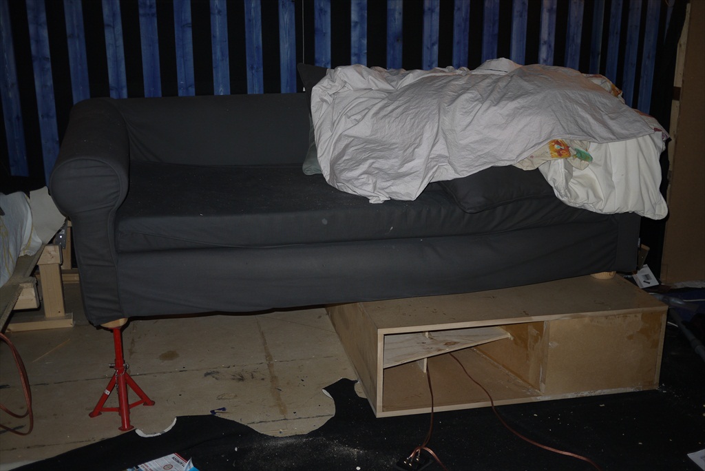
Great couch picture.
Regards,
Your measurements in Post #196 both show a bump in the 30-40Hz region. I get a similar bump in Hornresp when I double the driver impedance (Le). As the driver impedance in the sub 100Hz range is usually not anything like the manufacturer's Le specification (which is normally measured @ 1kHz), a rising Le in this range may be the cause.
At the very low end, below 20Hz it looks like your system may have a low cut filter. Do you have any way of testing for this?
Great couch picture.
Regards,
Attachments
Cool
Difference in sound? Does that matter?
I have no clue, have just done the measuring for now.
I am guessing (dont know) but that closing the mouth would affect the "connection" with the room/air but that is just my amateur thoughts...
I connected the minidsp and played for a few minutes (yeah, maybe more) and now I have this graph instead :
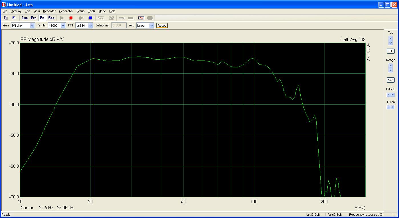
The minidsp has to be the coolest thing ever....
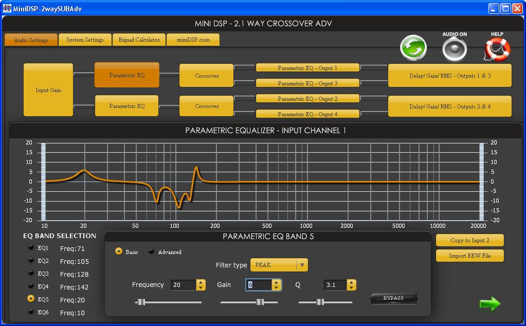
Added a bandpassfilter (-48db/oct on 10 and 130 Hz) and 5 PEQ points.
Here is the PEQ graph in minidsp:
Last edited:
Hi barco,
Your measurements in Post #196 both show a bump in the 30-40Hz region. I get a similar bump in Hornresp when I double the driver impedance (Le). As the driver impedance in the sub 100Hz range is usually not anything like the manufacturer's Le specification (which is normally measured @ 1kHz), a rising Le in this range may be the cause.
At the very low end, below 20Hz it looks like your system may have a low cut filter. Do you have any way of testing for this?
Great couch picture.
Regards,
Oliver, I would rather think the driver motor is not as strong as JBL states
. Try decreasing Bl and keep the horn parameters constant except from the
last segment which is longer in barcos horn then the original Kraken 212.
- Status
- This old topic is closed. If you want to reopen this topic, contact a moderator using the "Report Post" button.
- Home
- Loudspeakers
- Subwoofers
- Build your own 2x12" TH (The Kraken 212 TH)