On another forum where I am a moderator, a subwoofer was donated by a sponsor to one of the forum members. He put the sub in a tapped horn, and blew it to pieces in a matter of days.
I'd like to dedicate this thread to that poor sub's memory, and let it know that it did not die in vain.
In that sub's honor, I'm going to take a few minutes on my holiday to explore the behavior of tapped horns in the real world. The simulations and the reality aren't what they seem.
Before I dive into this topic, a few caveats:
- I've built and measured a pile of speakers over the past couple decades, and I've noticed that the computer simulations of bandpass and vented boxes rarely match reality, particularly in a room. This is because vents do not behave like the simulations would have you believe. For instance, the predicted length of a vent is affected by the location of the mouth and the throat. Tapering a vent improves performance a great deal, and tapering affects the tuning frequency also.
- Ironically, I've noticed that horns and tapped horns perform closer to the simulations than vented and bandpass boxes do. I believe this is because the helmholtz resonance depends on a lot of variables that aren't factored in by programs like WinISD, while HornResp and Akabak are more complex (and accurate.)
- Sealed boxes are incredibly forgiving. For instance, modest leaks do little to alter their response. If only other box types were so forgiving! IMHO bandpass boxes are one of the most unforgiving box designs, because leaks screw up the helmholtz resonance. I've seen leaks that were the size of a pinhead that have altered the frequency response! And when you think about the pressure that's being exerted on the chambers in a bandpass box, you can see why a leak that's invisible to the naked eye will have an effect on the output. With a sealed box, not so much, because a small leak is "competing" with the output from a cone that's dwarfs it.
On another forum where I am a moderator, a subwoofer was donated by a sponsor to one of the forum members. He put the sub in a tapped horn, and blew it to pieces in a matter of days.
I'd like to dedicate this thread to that poor sub's memory, and let it know that it did not die in vain.
was it high passed? A pa style tapped horn without a high pass, is like a duck in a shooting gallery...
Before we get into the measurements, lets do some CSI work on our victim.
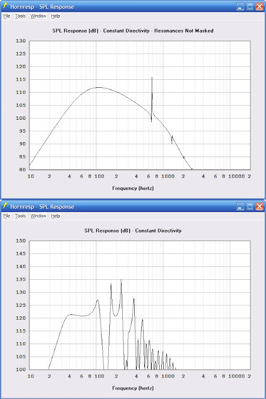 This is the predicted frequency response of the subwoofer in the manufacturer's recommended enclosure, and in the tapped horn that the victim died in. The murder weapon^H^H^H^H^H^H^H^H^H^H^H^H tapped horn has a nice bump in efficiency, about 10db at 60hz. In the tapped horn, the woofer will sound about twice as loud.
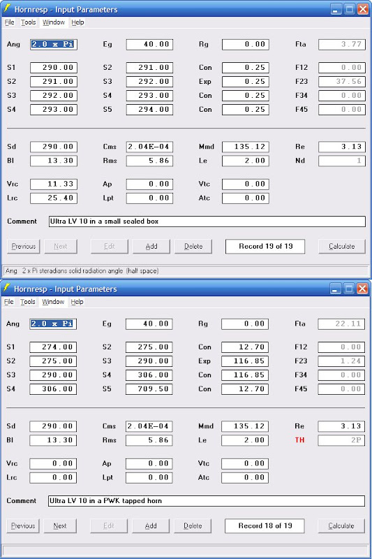 When the victim's father asked me about putting the victim in a tapped horn, it seemed to be a good fit. High FS, high BL, and low VAS. All are things you want in a TH woofer. The tapped horn is relatively compact, under three cubic feet. The sealed box is VERY small... And for a reason. (We'll get to that shortly.)
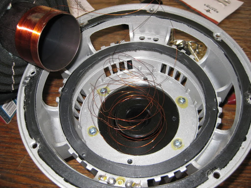
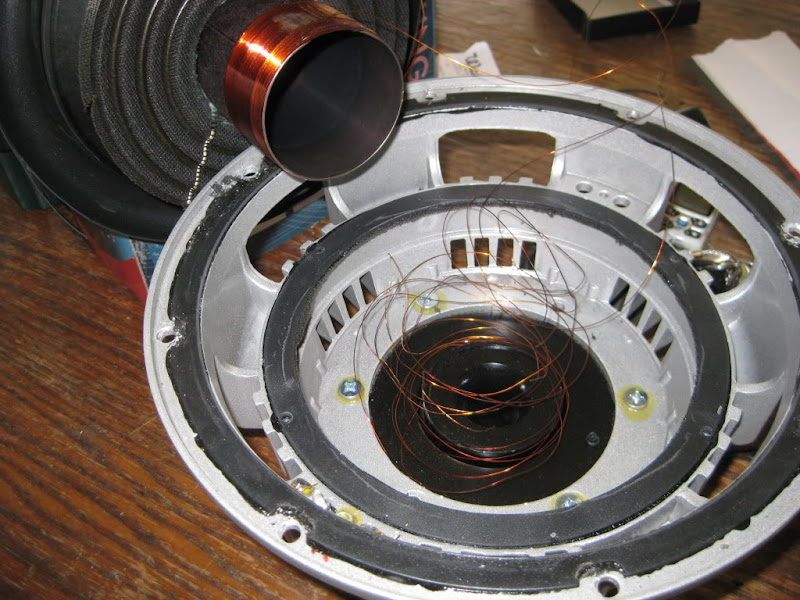
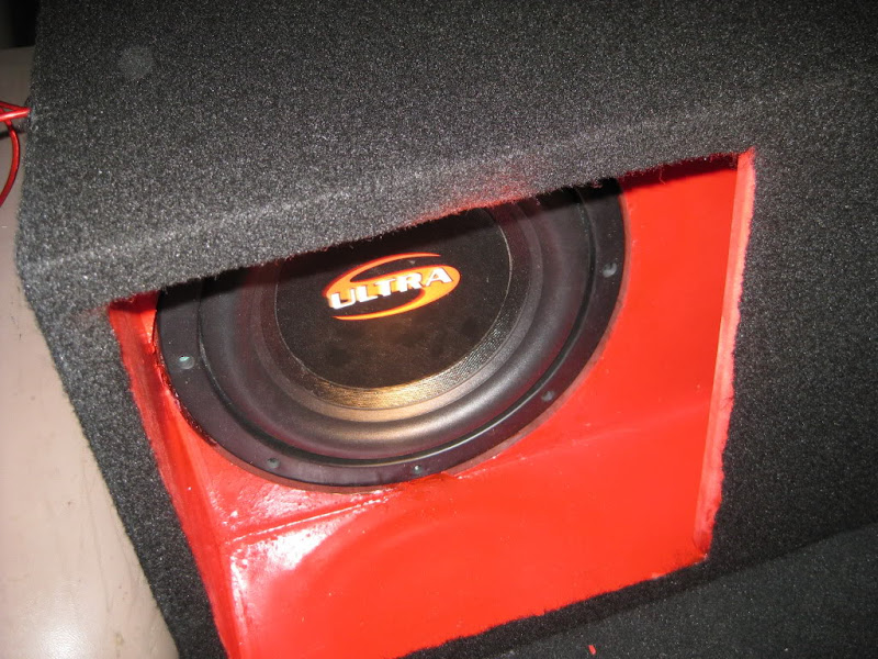 A picture of the victim during happier days
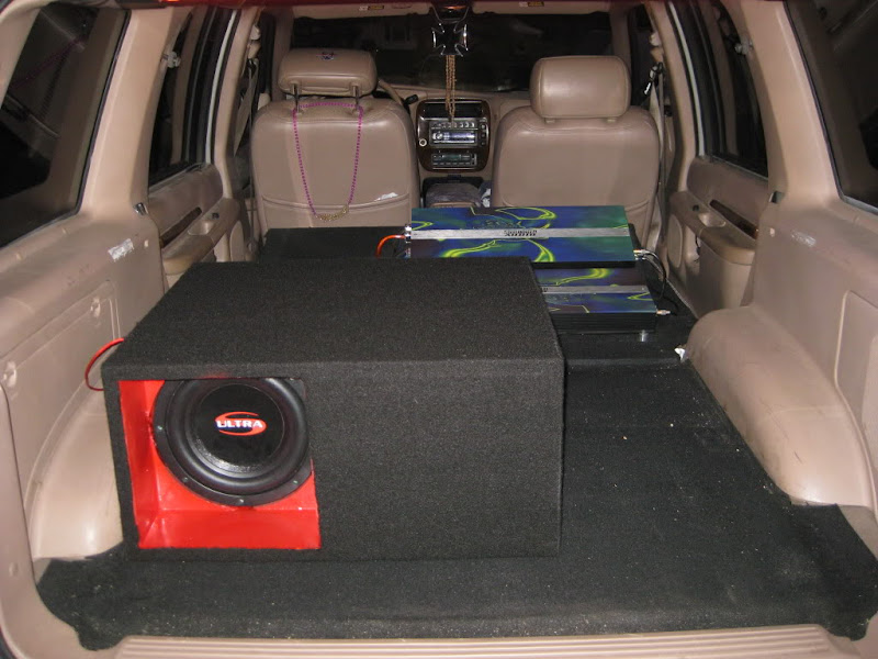 Note to self - a three cubic foot sub box fits a lot better in an SUV than in my Honda coupe
Hope I didn't upset anyone with these gory photographs.
was it high passed? A pa style tapped horn without a high pass, is like a duck in a shooting gallery...
Q: How can you tell the difference between a good amp for a tapped horn, and a bad amp?
A: The good one has a rumble filter.
After building the tapped horn, the victim's father noted that "the box design is small, limiting the deeper bass, I knew it should have been twice this size."
All you CSI types know that this is the first hint of the horrors to come. To investigate further, let's fire up hornresp.
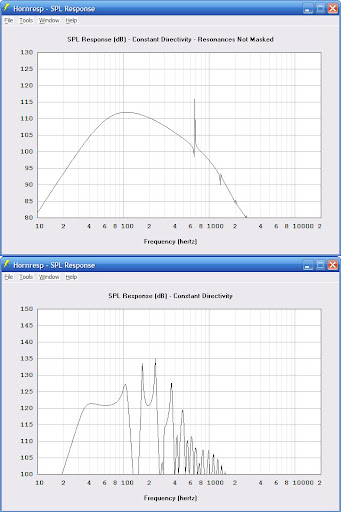 According to our simulations, the tapped horn is capable of generating 100db at 20hz, and 122db at 40hz.
This is one clue to the "lack of deep bass" comments. While the sub can generate lots of deep bass, the 40hz note is over 22db louder than the 20hz note. Factor in cabin gain, and the sealed box will be smoother... But the tapped horn is still more efficient.
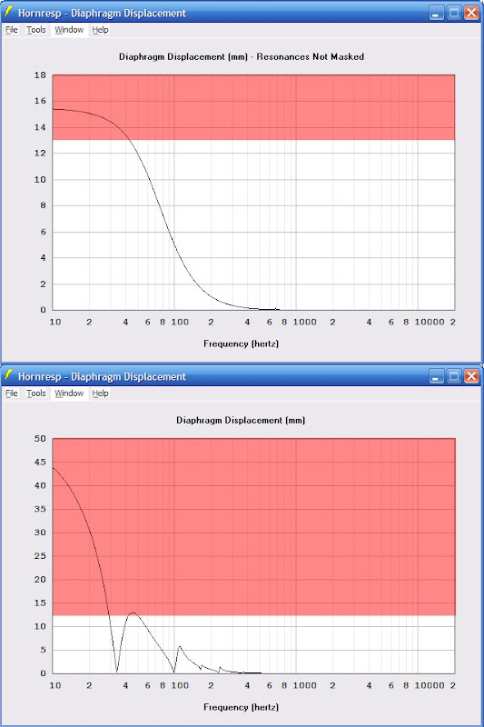 Here's the predicted excursion, with 500 watts into a 3ohm load. If you're listening to rock music, this sub will be rockin' out with 500 watts. Most of the energy is in the octave between 40 and 80hz, and the sub won't exceed it's limits in that octave.
But what if you put on a rap or techno CD? With the sealed box and 500 watts, a bass line at 25hz is exceeding the woofers limits. Not by a LOT though. You might hear a metallic "whacking" sound as the woofer starts to run out of excursion.
With the tapped horn? It's woofer detonation time! A single strike of a drum at 25hz will result in the voice coil jumping nearly TWICE as far as it's supposed to go
The scary part about this crime scene is that you probably wouldn't see it coming. Look at the excursion on the sealed box, and see how it graaaaaaadualy increases. And on the tapped horn?
Voice coil simply jumps out of the gap. With enough power, the woofer is irreparably trashed.
Another thing that I've noticed in my measurements is that a sealed box mounted in the trunk of a car sees an increase in the impedance curve. My hunch is that the air in the trunk "presses" against the cone, raising impedance and lowering excursion.
In other words, the sims predict that a sealed box can only handle 500 watts due to excursion. If my hunch about sealed boxes in trunks is correct, the "real" power handling could be as much as 750watts.
But with the tapped horn, the woofer would still explode, because it's waaaaaaaaaay beyond it's limits. A 25% reduction in excursion isn't going to save it.
All you CSI types know that this is the first hint of the horrors to come. To investigate further, let's fire up hornresp.
This is one clue to the "lack of deep bass" comments. While the sub can generate lots of deep bass, the 40hz note is over 22db louder than the 20hz note. Factor in cabin gain, and the sealed box will be smoother... But the tapped horn is still more efficient.
But what if you put on a rap or techno CD? With the sealed box and 500 watts, a bass line at 25hz is exceeding the woofers limits. Not by a LOT though. You might hear a metallic "whacking" sound as the woofer starts to run out of excursion.
With the tapped horn? It's woofer detonation time! A single strike of a drum at 25hz will result in the voice coil jumping nearly TWICE as far as it's supposed to go
The scary part about this crime scene is that you probably wouldn't see it coming. Look at the excursion on the sealed box, and see how it graaaaaaadualy increases. And on the tapped horn?
Voice coil simply jumps out of the gap. With enough power, the woofer is irreparably trashed.
Another thing that I've noticed in my measurements is that a sealed box mounted in the trunk of a car sees an increase in the impedance curve. My hunch is that the air in the trunk "presses" against the cone, raising impedance and lowering excursion.
In other words, the sims predict that a sealed box can only handle 500 watts due to excursion. If my hunch about sealed boxes in trunks is correct, the "real" power handling could be as much as 750watts.
But with the tapped horn, the woofer would still explode, because it's waaaaaaaaaay beyond it's limits. A 25% reduction in excursion isn't going to save it.
Hi Patrick Bateman,
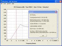
You would if you used the Hornresp Maximum SPL tool") . The attached screenprint shows your sealed box example - red indicates displacement limited. For the purpose of the exercise, Xmax is assumed to be 13 mm. (In any analysis such as this, it is important to understand the difference between input power and input voltage).
. The attached screenprint shows your sealed box example - red indicates displacement limited. For the purpose of the exercise, Xmax is assumed to be 13 mm. (In any analysis such as this, it is important to understand the difference between input power and input voltage).
As indicated in the Diaphragm Displacement section of the Hornresp Help file, behaviour at all input voltage levels is assumed to be linear. No allowance is made for low frequency high power amplitude compression.
Kind regards,
David
The scary part about this crime scene is that you probably wouldn't see it coming.
You would if you used the Hornresp Maximum SPL tool
. The attached screenprint shows your sealed box example - red indicates displacement limited. For the purpose of the exercise, Xmax is assumed to be 13 mm. (In any analysis such as this, it is important to understand the difference between input power and input voltage).In other words, the sims predict that a sealed box can only handle 500 watts due to excursion. If my hunch about sealed boxes in trunks is correct, the "real" power handling could be as much as 750watts.
As indicated in the Diaphragm Displacement section of the Hornresp Help file, behaviour at all input voltage levels is assumed to be linear. No allowance is made for low frequency high power amplitude compression.
Kind regards,
David
Attachments
Hi Patrick Bateman,
You would if you used the Hornresp Maximum SPL tool
As indicated in the Diaphragm Displacement section of the Hornresp Help file, behaviour at all input voltage levels is assumed to be linear. No allowance is made for low frequency high power amplitude compression.
Kind regards,
David
Oh, I should have mentioned, I didn't design the murder weapon
The dB Drag crowd discovered tapped horns, and a member on a forum that I moderate strapped 6000 watts worth of amplifiers to a ten inside a TH. With tragic results
Here's the person that designed - actually a lot of nice boxes here:
Peter W. Kulicki WorkBlog
Hi,
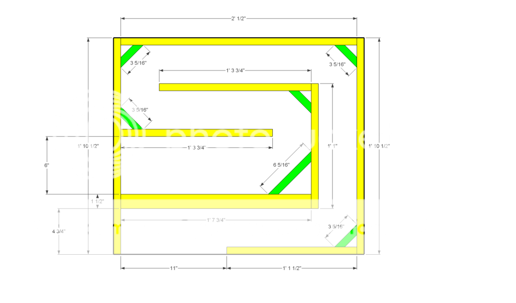
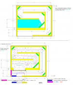
FYI:More CSI observations It looks like the designer of this TH by a mistake? used a 2P = 2 drivers in parallel simulation seen at the TH input screen here above, but the finished TH-box has only one driver? See picture 1(3) where the suggested 2P driver TH is compared to using only one driver.
The termination (load) from the pipe looks ending too early and not fully(acoustically) enclosing the driver. Actually the implemented speaker looks like a slightly positive taper OD(offset driver) TL terminated at a driver diameter less than the total internal length = 259 cm and thus tuned above fs. This is IMO not a TH.
As can be seen at the excursion plot from about 50-60 Hz: only a very steep(> 24 db/octave) HP filter would protect the 2P drivers from over excursion: See picture 2(3) where also plots of more realistic max SPL is shown for the 2P driver TH and the one driver closed box at the left side of the picture.
The driver in use is IMO almost a text box example of a driver primarily well suited for a small closed box . As Qts is about 0.42 a box volume should stay within 2xVas at max.
Picture 3(3) shows a 2P (two drivers in parallel)T-QWP (tapped quarter wave pipe) compared to the proposed 2P driver TH. Note: the pipe diameter must then be less than 2xSd for both sides of the drivers in order to minimize pass band ripple when tuned at fs.
b
FYI:More CSI observations
It looks like the designer of this TH by a mistake? used a 2P = 2 drivers in parallel simulation seen at the TH input screen here above, but the finished TH-box has only one driver? See picture 1(3) where the suggested 2P driver TH is compared to using only one driver.The termination (load) from the pipe looks ending too early and not fully(acoustically) enclosing the driver. Actually the implemented speaker looks like a slightly positive taper OD(offset driver) TL terminated at a driver diameter less than the total internal length = 259 cm and thus tuned above fs. This is IMO not a TH.
As can be seen at the excursion plot from about 50-60 Hz: only a very steep(> 24 db/octave) HP filter would protect the 2P drivers from over excursion: See picture 2(3) where also plots of more realistic max SPL is shown for the 2P driver TH and the one driver closed box at the left side of the picture.
The driver in use is IMO almost a text box example of a driver primarily well suited for a small closed box . As Qts is about 0.42 a box volume should stay within 2xVas at max.
Picture 3(3) shows a 2P (two drivers in parallel)T-QWP (tapped quarter wave pipe) compared to the proposed 2P driver TH. Note: the pipe diameter must then be less than 2xSd for both sides of the drivers in order to minimize pass band ripple when tuned at fs.
b
Attachments
Hi,
FYI:More CSI observations
Good catch. There actually is only one driver in the box.
The termination (load) from the pipe looks ending too early and not fully(acoustically) enclosing the driver. Actually the implemented speaker looks like a slightly positive taper OD(offset driver) TL terminated at a driver diameter less than the total internal length = 259 cm and thus tuned above fs. This is IMO not a TH.
Furthermore, the rear of the driver is actually loaded by a chamber. See diagram below:
How would you model this in HornResp?
Did the spider to former glue joint fail?
With no deformation of the back end of the former, why did the coil come apart?
I see a hard rub, and a coil delamination from improper adhesive and/or cure.
Every system should have a cut-off filter below the tuning frequency.
Amplifiers need clipping eliminators, or soft clipping on their inputs (to prevent amplifier clipping from producing loudspeaker dynamic off-set).
I'm not sure about the 'tapped horn' being the blame here.
David, How does HR calculate max SPL? It doesn't happen to do sqrt(P*Z) where Z is a calc'd impedance does it? If so, that's a bit odd as power amps are constant voltage systems, not constant power. What I mean is, if at 110Hz Z is 9 Ohms @ -42 degrees, but rated impedance is 4 Ohms and is being driven by 500W amp, that's still 45V max output. To get 500W across 9 Ohms is 67V. The amp is already clipped, you aren't going to get there. There really would be a voltage ceiling as well to maxSPL.
Did the spider to former glue joint fail?
With no deformation of the back end of the former, why did the coil come apart?
I see a hard rub, and a coil delamination from improper adhesive and/or cure.
Every system should have a cut-off filter below the tuning frequency.
Amplifiers need clipping eliminators, or soft clipping on their inputs (to prevent amplifier clipping from producing loudspeaker dynamic off-set).
I'm not sure about the 'tapped horn' being the blame here.
No the Glue did not fail / looks as if the coil started to unravell from the bottom hitting something in the gap...


How does HR calculate max SPL?
Hi davygrvy,
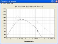
Hornresp calculates normal SPL response using a constant input voltage Eg. Maximum SPL response is calculated using a constant input power Pmax (except when the Xmax limit is reached at any frequency).
The attached screenprint of the sealed box example discussed earlier, illustrates the difference.
The gray trace shows the SPL for a constant input power of 500 watts. (Xmax set to 99.9 mm to ensure that the response is not displacement limited at any point). The black trace shows the SPL for a constant input voltage of 40 volts.
Note that the diaphragm displacement at 40 hertz for an input voltage of 40 volts is 13.4 mm, whereas the diaphragm displacement at 40 hertz for an input power of 500 watts is 29.0 mm.
As I said in my previous message, it is important to understand the difference between input power and input voltage
.Kind regards,
David
Attachments
Thanks for the close up of the coil damage.
I agree, it looks like it bottomed out on the backplate.
Dynamic off-set can destroy woofers in the blink of an eye. It is very important to hard limit (or clip) the input signal to the amplifier so the amplifier feedback loop never clips.
I used a 1KW amplifier on a sub tuned to 23hz with about 6dB of boost. It would bottom out the instant the amplifier clipped. The same sub could be bottomed out by a 100W amplifier driven into clipping. You could see the cone jerking back-and-forth in an irregular maner (it lookeed like it was between 2hz~8hz), even though there was a filter at 23hz (part of the EQ for the sub).
I have the signal set with an O-Scope / NO SQUAREWAVES
using an Alpine 9887 ( Imprint ) & Kove Audio Aphex Ax1 Signal Processor, have a CLEAL 6v through the Rca's / Clean Signal on the Oscope...
Gain on the amps is set on the floor maybe 1 notch up from Zero (0) / no bass boost
please keep in mind that i am only a Weekend SPL Warrior / during the week i have an SQL Enclosure loaded
An externally hosted image should be here but it was not working when we last tested it.
An externally hosted image should be here but it was not working when we last tested it.
An externally hosted image should be here but it was not working when we last tested it.
How would you model this in HornResp?
Hi,
I would model this outlay almost like a straight pipe where S1 and S2 have constant equal CSA, L12+L23 set to the first chamber length using the TH Wizard.
As the termination opening is IMO too large for a 'tapped purpose',I would end the length calculations as for an 'OD' system model ( See the picture) that is invoked at the main input screen.
A length reduction, about 9" i.e. Total L = L12+L23+L34+L45 -9" is then necessary as seen in the picture.
After returning from the TH Wizard screen to the main input screen in order to
calculate an 'OD' speaker the red colored label 'TH' must be changed to a red 'OD'.
Then if the calculation button is pressed, the driver to 'terminus' distance must be inserted pressing 'Tools' and from the drop down list select the 'Combined
Response...' and enter for this case a distance of about 4.25" or about 11 cm.
b
Attachments
Hi,
I would model this outlay almost like a straight pipe where S1 and S2 have constant equal CSA, L12+L23 set to the first chamber length using the TH Wizard.
As the termination opening is IMO too large for a 'tapped purpose',I would end the length calculations as for an 'OD' system model ( See the picture) that is invoked at the main input screen.
A length reduction, about 9" i.e. Total L = L12+L23+L34+L45 -9" is then necessary as seen in the picture.
After returning from the TH Wizard screen to the main input screen in order to
calculate an 'OD' speaker the red colored label 'TH' must be changed to a red 'OD'.
Then if the calculation button is pressed, the driver to 'terminus' distance must be inserted pressing 'Tools' and from the drop down list select the 'Combined
Response...' and enter for this case a distance of about 4.25" or about 11 cm.
b
Hmm... will try that when I have a few minutes to spare...
I forgot to include that the internal height of the box (not given in the picture) is 11".
- Status
- This old topic is closed. If you want to reopen this topic, contact a moderator using the "Report Post" button.
- Home
- Loudspeakers
- Subwoofers
- Tapped Horns - Simulation VS Reality