a small set of external speakers that come with my TV use a 2" Driver with an Aluminimum Hexagonal sandwich type cone,and a 3" Passive Radiator the passive radiator is two Flat aluminimum pieces with a fairly dense,rigid piece of foam between them....it was simply a flat diaphram with a Cloth Roll Surround...no spider which is perfectly fine as the 2" Driver most likely doesnt move enough air to push the Radiator to the point of needing a spider to stay linear,ill never know how good...or bad they sounded for that matter....the 2" Drivers had Foam Surrounds...which had basically Rotted away into nothing...the speakers still played though...the Aluminimum Diaphrams of course gave Bright High Notes and decent mids...the bass was non existant...or midbass for that matter...probably due to the missing surround...a search of the sony part # Stamped on the speaker reveals the speaker is still avalible....it makes me wonder if High Density foam would be good for a passive radiator...its Awfully light...and quite rigid...and those thin aluminimum sheets on either side certainly help...the question is how can you Mold your own surround?...prehaps have a Metal Mold Cast..and pour a Rubber mix in and let it harden to the Form of the Surround?...and what about the secondary suspension...(as i like to call it)...more generally called the spider...you can probablu get one of those at a speaker repair site....dont know how you can make your own,Total Linearity wouldnt probably matter since theres no voice coil to rub against the Motor structure...
wouldnt a bigger PR also result in lower Q ressonance?
Instead of ordinary spider its possible to use spider threads
Make a block of poly foam with backside shaped like a woofer cone
A wooden stick in the middle fore mounting the spider
Centering isnt exstremely important as there is no voice coil
But at this low frequency, maybe a spider isnt needed at all
Chassis could still be wood, or the box itself
Front of poly block could be anything, wood or aluminium
But at this low frequency, does a spider really make a difference
Fs surely gets lower without, with thread spider as an exception
Last edited:
Done it - it works!

Years ago i needed to tune something like 20L to about 25Hz. As the enclosure was a 4th order bandpass & was being fed by 8 (yes eight) 8" drivers i decided that a port was out of the question as it'd be rather big to say the least
So i designed & built an oval (race track) style passive radiator. Instead of using a bicycle innertube i used 2 motorcyle innertubes & cut each tube so i had more than half of each tube left. I know this is kind of complex so bear with me..I made two oval surrounds out of MDF & cut a nice big piece of 4mm aluminium for the diaphram. I then cut more pieces of alloy to clamp the two pieces of innertube together by bolting through & sandwiching them between the alloy plates. Copious amounts of evostik type glue to seal it completely.
The same was done on the outer surround which was obviously the frame.
Tuning it was a doddle as all i needed to do was inflate the now sealed innertube to get the correct resonance frequency via a standard air valve..Ok so it needed adjusting about once a year, in fact it leaked less than a normal innertube.
No spider needed
I ended up selling the sub to a friend who made rather good use of it until he moved to a smaller property, at which point he sold it back to me dead cheap
I'll see if i can get some pictures for you all, give me a few days.. I wouldn't hesitate to do a similar thing again, though i'd make the thing round!
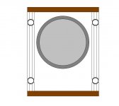
It might be called crazy, but i can tell you that it worksThe third one is a crazy idea from another thread
Surround is a bicycle tube
Airpressure should keep it in place
Years ago i needed to tune something like 20L to about 25Hz. As the enclosure was a 4th order bandpass & was being fed by 8 (yes eight) 8" drivers i decided that a port was out of the question as it'd be rather big to say the least
So i designed & built an oval (race track) style passive radiator. Instead of using a bicycle innertube i used 2 motorcyle innertubes & cut each tube so i had more than half of each tube left. I know this is kind of complex so bear with me..I made two oval surrounds out of MDF & cut a nice big piece of 4mm aluminium for the diaphram. I then cut more pieces of alloy to clamp the two pieces of innertube together by bolting through & sandwiching them between the alloy plates. Copious amounts of evostik type glue to seal it completely.
The same was done on the outer surround which was obviously the frame.
Tuning it was a doddle as all i needed to do was inflate the now sealed innertube to get the correct resonance frequency via a standard air valve..Ok so it needed adjusting about once a year, in fact it leaked less than a normal innertube.
No spider needed
I ended up selling the sub to a friend who made rather good use of it until he moved to a smaller property, at which point he sold it back to me dead cheap
I'll see if i can get some pictures for you all, give me a few days.. I wouldn't hesitate to do a similar thing again, though i'd make the thing round!
I for one would be interested in seeing your design event horizon.
Somewhat on the topic, I have a pair of passives (not sure where from, found them on the side of the road) they are made by having a cylindrical piece of plastic around 3"(75mm) deep by around 12" (300mm) diameter, with a flange on one end of the cylinder. Inside of this is a piece of white packing foam as a radiator, that has a rubber face on the flange end (for appearance) and then they use two rubber surrounds, one at each end of the cylinder to hold the radiator in place. Basically a pretty good pistonic motion from what I can see.
I also had a thought about the usage of the voice coil with a resistor across it's terminals for damping, why not take it one further and use a non permanent magnet (field coil) instead of the standard magnet on your speaker. Then you can vary the damping by varying both the resistance that the voice coil sees and the magnetic field that the voice coil works in.
Peace,
Dave
Somewhat on the topic, I have a pair of passives (not sure where from, found them on the side of the road
) they are made by having a cylindrical piece of plastic around 3"(75mm) deep by around 12" (300mm) diameter, with a flange on one end of the cylinder. Inside of this is a piece of white packing foam as a radiator, that has a rubber face on the flange end (for appearance) and then they use two rubber surrounds, one at each end of the cylinder to hold the radiator in place. Basically a pretty good pistonic motion from what I can see.I also had a thought about the usage of the voice coil with a resistor across it's terminals for damping, why not take it one further and use a non permanent magnet (field coil) instead of the standard magnet on your speaker. Then you can vary the damping by varying both the resistance that the voice coil sees and the magnetic field that the voice coil works in.
Peace,
Dave
I didn't explain that very well. You use another woofer, cheaper usualy, as the passive, wire a wirewound pot across the terminals. The resistance across the voicecoil acts as a brake giving you variable tuning. After the system has been run in and you are happy with the tuning you can replace the pot with a fixed resistor.
If you want to see the effect yourself, take any woofer, by hand check how easy it is to move the cone. Now short the terminals and check again, much harder to move.
Terry
Hi All,
When I first suggested the use of a large woofer as a "tuned sub" by using a resisive pot across the voice coil many years ago on the old Bass List, there were many that wanted to dismiss the whole idea. Then, when I next suggested that by using a dual VC woofer's second VC to tune the Q of the woofer itself, with a variable resistor, it got worse. This was just at the time Bass List members, including a young sonar designer by the name of Dan Wiggins, were planning on developing a "Bass List Subwoofer." However, unlike some of the other members, Dan Wiggins liked my idea and worked out the math involved. When the dust cleared, the final result was the Dan Wiggins' design of the Shiva Subwoofer Driver, which used dual voice coils. The Shiva White Paper covers this use of a variable "Q" 2nd voice coil rather extensively.
BTW: The Shiva was originally cited as "The Official Bass List Subwoofer" and Terry Olson had made his only "real" contribution to audio.
Best Regards,
TerryO
Last edited:
Attachments
"I didn't explain that very well. You use another woofer, cheaper usualy, as the passive, wire a wirewound pot across the terminals."
what is special about the wire wound resistor as opposed to a linear taper?
typically, what value resistor and power are required?
"what is special about the wire wound resistor as opposed to a linear taper?"
A WW is available in a higher wattage part. A WW can be a linear taper, log taper, or semi-log taper.
"typically, what value resistor and power are required? "
I would use a 15W L-pad connected with terminals 1 and 2 to the APR.
A WW is available in a higher wattage part. A WW can be a linear taper, log taper, or semi-log taper.
"typically, what value resistor and power are required? "
I would use a 15W L-pad connected with terminals 1 and 2 to the APR.
"what is special about the wire wound resistor as opposed to a linear taper?"
A WW is available in a higher wattage part. A WW can be a linear taper, log taper, or semi-log taper.
"typically, what value resistor and power are required? "
I would use a 15W L-pad connected with terminals 1 and 2 to the APR.
so basically only a few ohms resistance is required?
However, unlike some of the other members, Dan Wiggins liked my idea and worked out the math involved. When the dust cleared, the final result was the Dan Wiggins' design of the Shiva Subwoofer Driver, which used dual voice coils. The Shiva White Paper covers this use of a variable "Q" 2nd voice coil rather extensively.
Who was it who worked out this math?
Who was it who worked out this math?
Ron,
I get the sense that you remember this from... (the Bass List?)
Dan certainly did the Math, although I checked his work and made any necessary corrections.
For those who may not know, I claim the title as the World's Worst Mathematician. Many have attempted to challenge my supremacy, but all have been confounded by my incomparable mastery of math ineptitude.
Best Regards,
Terry
Ok , Terry a challenge,
What is "(3.14658/3^3)(5/2*7)="
I've had a 5 year old answer this correctly
Ok , Terry a challenge,
What is "(3.14658/3^3)(5/2*7)="
I've had a 5 year old answer this correctly
~ .025
try again
of course the answer depends upon the order of precedence.
if you place this expression in a spreadsheet manager, the result will be text since the formula is bounded by quotes.
so, depending upon the "rules of engagement" here, there are several answers.
you have one.
ok, apparently Terry doesn't want to play.
Q: What is "(3.14658/3^3)(5/2*7)="
A: an equation.
I was afraid if I replied, that I might accidently have gotten the correct answer and "blown" my standing!
All you envious types would just love to pull me me down off of my pedestal, but I've foiled you again!
Best Regards,
Terry "The Champion" Olson

- Status
- This old topic is closed. If you want to reopen this topic, contact a moderator using the "Report Post" button.
- Home
- Loudspeakers
- Subwoofers
- Passive radiator, build your own