I'm planning on building some subs for the man cave, I have these items that are left over from projects over the years.
1 pair (or two) of these Parts-Express.com:*Dayton ST255-8 10" Series II Woofer | woofer st255-8 10" woofer midbass dayton series II series 2 dayton audio dayton loudspeaker series 2 10" subwoofers
1 pair of 12" passive radiators (forgot the brand)
My problem is that I'm very good with tools and not very skilled with computers! I just need some direction to figure out box size. I want to have upright boxes with as little footprint as possible. These will be driven with adcom 565's that were driving the Maggies before I went to tubes. They will be used mainly for music and TV never for HT. I realize without specs for the passives it will not be an exact science and I'm not looking to go that low just clean and tight.
This driver models well in a simple tapped horn. A pair models even better.
My model was very quick with very little refinement. I am sure it can be improved upon/further optimized. I'd be happy to post it if others want to mess with it.
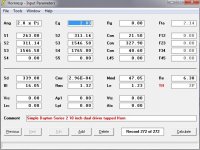
Limit the low bandwidth to 30 Hz to control excursion. You will run out of linear excursion, but still should be within the mechanical limits of the drivers at rated power (15 mm @ 500 W to the pair). I've driven Dayton 10" woofers past this level of excursion without scary noises. SPL output should be more than adequate, approx 125 dB @ 500 watts ground-plane, significantly louder if placed near a wall or corner.
At over 12 cubic feet, the box will be large, but it should be an easy build and will fit through doors. The simplest tapped horns can be constructed with 7 boards and no angle cuts. I'd recommend some bracing, so you're up to 9 boards if you keep it simple. Different shape cabinets require different folds, potentially getting complicated.
Sound quality - well, I do not know. I have listened to tapped horns with several direct-radiator systems and they blend well. Magnepans may be a bit more of a challenge, I don't know, I've never had the pleasure of listening to a pair.
My model was very quick with very little refinement. I am sure it can be improved upon/further optimized. I'd be happy to post it if others want to mess with it.
Limit the low bandwidth to 30 Hz to control excursion. You will run out of linear excursion, but still should be within the mechanical limits of the drivers at rated power (15 mm @ 500 W to the pair). I've driven Dayton 10" woofers past this level of excursion without scary noises. SPL output should be more than adequate, approx 125 dB @ 500 watts ground-plane, significantly louder if placed near a wall or corner.
At over 12 cubic feet, the box will be large, but it should be an easy build and will fit through doors. The simplest tapped horns can be constructed with 7 boards and no angle cuts. I'd recommend some bracing, so you're up to 9 boards if you keep it simple. Different shape cabinets require different folds, potentially getting complicated.
Sound quality - well, I do not know. I have listened to tapped horns with several direct-radiator systems and they blend well. Magnepans may be a bit more of a challenge, I don't know, I've never had the pleasure of listening to a pair.
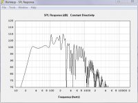
Here is the model inputs and results.
Remember - this is just a first, rough model of a simple (single taper) tapped horn. I am sure it can be improved.
edit - Attachments....
Remember - this is just a first, rough model of a simple (single taper) tapped horn. I am sure it can be improved.
edit - Attachments....
Attachments
Last edited:
I appreciate the suggestions, zora: just for *****&grinz I asked AE what they would suggest but I don't have much of a budget for drivers (it went towards tubes!). The reason that I need a small footprint is this room is 12'X24' with Maggies 7' apart on the one long wall. The right short wall has my desk (5.5'X6.5' corner) and the other short wall has a 8'@300 gal. aquarium. Down the road I plan on putting the Maggies in a dedicated listening room when/if I can move! I wouldn't rule out building nicer subs but they would be for music first. I've got a SVS up in the theater and it shakes the house but I don't care for that type of bass in two channel. I have a diy sub that I built with my original SVS driver when I updated drivers but I've been told I need some way to raise the gain feeding the 565 from the avr because even at max setting on the preout it is not enough. It is nice clean bass just not enough, originally I thought of building two of these but now I may sell both SVS's and build two killer musical subs powered by the 565's.
Last edited by a moderator:
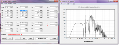
Here's a reverse tapped pipe (dual driver version) that should get you into the mid 30 Hz in room. This could be split into two enclosures (each half the starting and ending cross sectional area).
I've had magneplanars (borrowed MMG and owned vintage MG1) in the past and regular box subs just didn't cut it. Horns (low distortion) blended fine and added the punch that these lacked, somewhat. From my experiments a few years ago, I'm guessing open baffle dipole woofers would work okay too (apart from being somewhat SPL limited, unless using multiple drivers)
If you're handy with tools, you owe it to yourself to try this or the other tapped horn enclosure (check with the experts first that there are no glaring flaws in this design )
I've had magneplanars (borrowed MMG and owned vintage MG1) in the past and regular box subs just didn't cut it. Horns (low distortion) blended fine and added the punch that these lacked, somewhat. From my experiments a few years ago, I'm guessing open baffle dipole woofers would work okay too (apart from being somewhat SPL limited, unless using multiple drivers)
If you're handy with tools, you owe it to yourself to try this or the other tapped horn enclosure (check with the experts first that there are no glaring flaws in this design
)Attachments
Last edited:
Hmm - looking at the two sims, either Zobksy or I have a typo somewhere, our driver parameters do not match for Cms and Mmd. I used the information provided in the Parts Express PDF data sheet. I think I got the info typed in right (unless my typo is staring me in the face).
Similar to Zobsky's design, the tapped horn can be split into two cabinets, with one driver per and about half the total volume. Even with a stereo pair, I'd run them mono. With a single fold (like Cowan's tapped horns), floor footprint would be minimal (2 sq feet). If you have 4 drivers, use two per cabinet. With the typical fold I envision, the drivers will be low in the cabinet so it should be relatively stable.
You can make the single or dual driver enclosure considerably smaller, peak SPL capability drops and excursion goes up a bit, but unless you're looking for that last dB, it really does not matter. I got the enclosure down to 8.5 cubic feet for two drivers, which is about 0.75 by 2 by 6 feet, though layout of the fold may change this a bit.
Based on my experience designing, building, and measuring tapped horn subs (some documented over in the collaborative thread), the large spike the model predicts just after the passband is attenuated in reality. Some of my subs have not had the spike at all, though the model predicted a 10 dB spike in the response. The rising response after the first peak is usually present, and can be easily tamed with an electronic crossover.
Hmm - looking at the two sims, either Zobksy or I have a typo somewhere, our driver parameters do not match for Cms and Mmd. I used the information provided in the Parts Express PDF data sheet. I think I got the info typed in right (unless my typo is staring me in the face).
I'm probably the one with the typo since I manually entered data based on your input. Will re-check at home.
Zobsky, What type,size box would that call for?
approximately 3.5 ft high and a footprint of 0.6 sq ft (assuming both drivers in one cabinet, halve the footprint if building 2 cabinets)
Looks: something like this: http://www.diyaudio.com/forums/subwoofers/149077-sub-design-recommendation-needed.html#post1904773
How can I figure the cabinet dimensions for two of these with one driver each? I've tried to download hornresp with no luck. I'm very interested in this design after some research last night. I have all the tools (remodeling cont. for 25+yrs) so I need to just learn the design. Thx again.
Check out William Cowan's site, William Cowan's Homepage
as well as VolvoTreter's, Tapped Horns
Both of these sites have good explanations.
Ultimately, either design can be simplified into a box with a slanted baffle partially dividing it, once you choose which direction, it is a simple matter of calculating areas and lengths.
as well as VolvoTreter's, Tapped Horns
Both of these sites have good explanations.
Ultimately, either design can be simplified into a box with a slanted baffle partially dividing it, once you choose which direction, it is a simple matter of calculating areas and lengths.
Here are the corrected sims. The one thing I would have you verify with the experts would be to find the max excursion limited SPL . I never have good luck with figuring out how to do this with Hornresp but haven't had the time to investigate.
That said, playing around with Hornresp, I can get into the 30 Hz area without much difficulty but the enclosure will end up being a foot taller or so.
That said, playing around with Hornresp, I can get into the 30 Hz area without much difficulty but the enclosure will end up being a foot taller or so.
Attachments
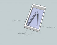
Regarding design criteria, this are some points when building the tapered TQWT design. Tapped horn design would be very similar, except of course the pipe has a positive (instead of negative) taper
My commandments of T-TQWT building
Bjorno and I seem to to be only ones who've built this enclosure. It's rather easy and smaller than conventional TH,.. and goes deeper while still maintaining the low excursion / distortion benefits, ... of course you can't go as loud as true horns,..but its a decent compromise.
Feel free to tweak the horn resp model to meet your goals . The important thing is to build, whether it be littlemike or my design etc ... If you want, you can design in a falling response to compensate for room-gain, .but you better know what your room does before doing that. In any case, it's easier to take away bass than add in missing bass
FWIW, my previous subs have been:
sealed: adire shiva (sucked)
16 ft transmission line: adire shiva (not bad)
EBS tuned sonotube: adire shiva (good for home theater down below 20 Hz, but not efficient enough for my hi eff speakers)
bill fitzmaurice auto tuba horn : MCM 8" (decent with music, planars, "fast sounding")
bill fitzmaurice table tuba horn: MCM 8" (decent with music / home theater down to 25Hz)
T-TQWT reverse tapped pipe: single tangband W69 (not as efficicient as the table tuba (should've used 2 drivers) but more even and "solid" response, ... not a fair comparison as it was tuned a bit higher at 35 Hz), . also sounded real nice as a car sub.
karlson K15: great for music to 45 - 50 hz: kicks like mule
So,.. when are you going to build a TH?
My commandments of T-TQWT building
- At the start of the pipe, cross sectional area = S1
- At the end of the pipe, cross sectional area = S4
- Area of the circular port towards the end of the pipe = S4.
- The center of the circular opening is situated at L34 away from the end of the pipe. Ideally, it should be at the end, but by situating the opening next to the drivers, the drivers can "breathe" more freely.A larger removal access panel can be situated around this area to allow easy access to the drivers.
- Certain amount of stuffing may be used in the pipe, as necesary
- Bracing between the outer walls and the divider can help reduce cabinet wall vibration. Then, you can get away with using 1/2" wood / MDF etc .. Remember, bracing is more important than sheer mass.
- For simplicity, you can assume the box to taper linearly from S1 to S4
- For simplicity, you can assume that at the top of the box where the taper changes direction, the equivalent length consumed by the bend = W/2 where W is the width of the box.
- Use a glue that seals . Air tightnes is CRITICAL. I repeat, CREETEECAL. I use PL brand polyurethane glue since it expands when curing sealing any voids.
Bjorno and I seem to to be only ones who've built this enclosure. It's rather easy and smaller than conventional TH,.. and goes deeper while still maintaining the low excursion / distortion benefits, ... of course you can't go as loud as true horns,..but its a decent compromise.
Feel free to tweak the horn resp model to meet your goals . The important thing is to build, whether it be littlemike or my design etc ... If you want, you can design in a falling response to compensate for room-gain, .but you better know what your room does before doing that. In any case, it's easier to take away bass than add in missing bass
FWIW, my previous subs have been:
sealed: adire shiva (sucked)
16 ft transmission line: adire shiva (not bad)
EBS tuned sonotube: adire shiva (good for home theater down below 20 Hz, but not efficient enough for my hi eff speakers)
bill fitzmaurice auto tuba horn : MCM 8" (decent with music, planars, "fast sounding")
bill fitzmaurice table tuba horn: MCM 8" (decent with music / home theater down to 25Hz)
T-TQWT reverse tapped pipe: single tangband W69 (not as efficicient as the table tuba (should've used 2 drivers) but more even and "solid" response, ... not a fair comparison as it was tuned a bit higher at 35 Hz), . also sounded real nice as a car sub.
karlson K15: great for music to 45 - 50 hz: kicks like mule
So,.. when are you going to build a TH?
Attachments
Last edited:
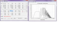
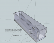
I'm planning two of these, I'll build one to test and then the second. The drawing on the right is the one? I'll make a rough sketch tomorrow and go over it with you. I'll probably just use a samson servo 600 I've got sitting around because the 565 monoblocks are overkill I think.
yes, the one on the right, the other render is an alternate method which has the driver cones facing each other for mechanical vibration cancellation
if you do decide to play with stuffing (optional) , stuff the wider half of the enclosure, not the narrower half
when you draw up a plan, make sure the drivers fit
if you do decide to play with stuffing (optional) , stuff the wider half of the enclosure, not the narrower half
when you draw up a plan, make sure the drivers fit
Last edited:
- Status
- This old topic is closed. If you want to reopen this topic, contact a moderator using the "Report Post" button.
- Home
- Loudspeakers
- Subwoofers
- Man cave subs to compliment Maggie 2.7OR's