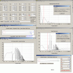
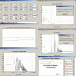
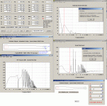
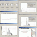
Is there a way to simulate this change in the L12/L34 values?
Because the if you increase the length of the horn by 10%, then you get 738.1mm for the L12 and L34 values and 5787.1mm for L23...Do I place the driver at the new (%10 longer) L12/L34 values? Because that is where they produce the actual S2/S3 values...
*NOTE* I accidentally mixed up length and area representation. When I said S2/S3 in the earlier posts, I meant L12 and L34...Sorry again
Is there a way to simulate this change in the L12/L34 values?
Because the if you increase the length of the horn by 10%, then you get 738.1mm for the L12 and L34 values and 5787.1mm for L23...Do I place the driver at the new (%10 longer) L12/L34 values? Because that is where they produce the actual S2/S3 values...
You can punch in the desired length directly in the main input screen. The driver locations will show up in the tapped horn wizard as shown in post # 57.
Once you read the manual it becomes a bit easier. Bjorno gets me every time with something I didn't bother checking up before I jump in.
You can optimize this horn by reducing it quite a bit by the way.
Mark
Hi,FYI,
First picture: Shows how to fold IME.
Second picture: What to be aware of.
Third picture: An alternative stuffed T-TQWT. The upper FR peak at 90 Hz will in the realty be benign as the box should be stuffed like a TL.
b
What do you mean by IME and What do you mean by T-TQWT??? Also, when you say FR you mean frequency and TL as in transmission line?
Sorry if I am not understanding the lingo, I am very new to the world of audio...
I did a new simulation with the new L12/L23/L34 values and all that seems to happen is almost nothing significant. If the current size of the horn is alright, then I will just leave it at that because size is not so much of a concern, but of course the 11' tall single fold I created is a bit too much...
Last edited:
Ive been looking into the idea of a similar 20hz horns using 2 dayton dvc 38588 15 inch woofers. I bought these recently and heres the parameters.

This is the response with 2.83 volts 1pi

And here it is at xmax 0.5 pi

I think this is about as good as i can get with these woofers. Bear in mid there will be 2 of these one in each corner of the room using the floor and corners of the brick and concrete building as the bottom and two sides of the sub (ill be making them triangular in shape)
Let me know if these plots look ok or not.
This is the response with 2.83 volts 1pi
And here it is at xmax 0.5 pi
I think this is about as good as i can get with these woofers. Bear in mid there will be 2 of these one in each corner of the room using the floor and corners of the brick and concrete building as the bottom and two sides of the sub (ill be making them triangular in shape)
Let me know if these plots look ok or not.
What do you mean by IME and What do you mean by T-TQWT??? Also, when you say FR you mean frequency and TL as in transmission line?
Sorry if I am not understanding the lingo, I am very new to the world of audio...
Hi slisgrinder,
Maybe I'm too confusing for more guys like you and sometimes make no sense when I trying to make myself short using aberrations like IMO = In My Opinion or IME = In My Experience.
I use those aberrations repeatedly in my postings to diyAudio just for the sake of being clear.
I find it essential to differentiate between what I have experienced or only have an opinion of.
FR = Frequency Response and T-TQWT ( Tapped-Tapered_Quarter_Wave_Tube) = reversed tapered tapped horn in HR.
b
Ive been looking into the idea of a similar 20hz horns using 2 dayton dvc 38588 15 inch woofers. I bought these recently and heres the parameters.

This is the response with 2.83 volts 1pi

And here it is at xmax 0.5 pi

I think this is about as good as i can get with these woofers. Bear in mid there will be 2 of these one in each corner of the room using the floor and corners of the brick and concrete building as the bottom and two sides of the sub (ill be making them triangular in shape)
Let me know if these plots look ok or not.
Hi oubile,
I'm not certain that the T/S data you are using is correct, I could be wrong but for a while ago I did simulate the Dayton DVC 385-88 for a friend after I made a consistency check of the driver data.
See submitted my plots.
A simple check can be made if I have maid a mistake :
Hooke up the DVC coils in series and measure the summed coil resistances with aid of an Ohm-meter.
If you read a value around 5.6 Ohm I'm pretty sure my entered data is correct. If not, Mail the driver retailer (I found the published data not to be trustworthy).
b
Attachments
Hey Bjorno
Guess what both of our spec are out!
Here are the spec from the Dayton Website which i would assume are 100% correct + / - the marketing department
http://daytonaudio.com/files/specs/DVC385-88_specsheet.pdf
Ill redo and post again i think.
btw does anyone know if these are correct or should i be doing something regarding the two voice coils i.e. setting the re to 5.6 ohms and changing any other parameters to match?
Thanks.
Well it looks like the dayton specs are right but not right, they seem to be for one half of the dual voice coil and therefore show the wrong bl and re data on their spec sheet.
I've remoddled the horn and this is what i get now.

Heres the response at xmax 0.5 pi (they are going to be concrete corner loaded) not too shabby for 1 (im build two of them )
)

I've remoddled the horn and this is what i get now.
Heres the response at xmax 0.5 pi (they are going to be concrete corner loaded) not too shabby for 1 (im build two of them
Hey Bjorno
Guess what both of our spec are out!
Here are the spec from the Dayton Website which i would assume are 100% correct + / - the marketing department
http://daytonaudio.com/files/specs/DVC385-88_specsheet.pdf
Ill redo and post again i think.
btw does anyone know if these are correct or should i be doing something regarding the two voice coils i.e. setting the re to 5.6 ohms and changing any other parameters to match?
Thanks.
Hi oubile,
b
PS. Connecting the coils in series will change the Qts to a too large value for a T-TQWT but could work well in an OD box.
Attachments
Last edited:
well this isn't related to the current topic of this thread but this is what I got in the mail yesturday: http://www.samsontech.com/products/productpage.cfm?prodID=1994&brandID=4
let me know what you guys think...its really handy for music practice and university lectures...
let me know what you guys think...its really handy for music practice and university lectures...
I am going to succumb to the tried and true nature of the LAB12 build by layertone and use 2x of those in my HT plans. Its just too good...
Last edited:
- Status
- This old topic is closed. If you want to reopen this topic, contact a moderator using the "Report Post" button.
- Home
- Loudspeakers
- Subwoofers
- diy 20 Hz tapped horn plans


