I'm trying to design a vented box wiht a subwoofer and i'm having some trouble. Most books and papers ignore voice coil inductance effect in the frequency response of the system but when i simulate my design including the inductance the response goes to hell! The shape around -3dB cutoff frequency changes and now there is a dip appart from the upper frequencies cutoff. If anyone can help me to sort this out or anyone knows a good book or page about inductance effect i would be grateful. Also, if there's any way to cancel this effect, it's welcome.
Of course i'm not using any CAD or program to do the design, just the theory, a calculator and Matlab to do the simulation , so this is a theory problem. Thanks in advance
Of course i'm not using any CAD or program to do the design, just the theory, a calculator and Matlab to do the simulation
, so this is a theory problem. Thanks in advanceI'm trying to design a vented box wiht a subwoofer and i'm having some trouble. Most books and papers ignore voice coil inductance effect in the frequency response of the system but when i simulate my design including the inductance the response goes to hell!
I've been looking at the same thing with a future closed-box subwoofer design in mind and I agree - it's a mess. I've been using three software tools to investigate this.
The first is LTspice, for which I posted a model of a closed-box sub using a Dayton Titanic 15" driver here. I was trying to get a Linkwitz transform to work, but the results were way off from the theory. I guessed that the presence of the voice coil inductance was not just adding a pole on the negative real axis to the system transfer function, but also shifting the existing pole pair that determines the quadratic polynomial in its denominator.
The second piece of software I'm using is a freeware symbolic circuit analysis program called SapWin that I posted about here. The example I posted has the same form as the LTspice subwoofer example linked above. I had SapWin derive the symbolic transfer function from the input voltage to the output volume velocity, taking into account the voice coil inductance. This transfer function is third-order and has the same poles as the transfer function from input voltage to anechoic on-axis pressure.
Then I made a Mathcad worksheet that plugs in the T/S parameters of the Dayton driver and the box volume, and numerically computes the poles of the system transfer function. This uses the formulas for the transfer function coefficients found by SapWin together with Mathcad's numerical root-finding for polynomials. This gave an additional pole on the negative real axis as expected. It also confirmed the hypothesis that the quadratic poles were shifted. How much were they shifted?
Below, f1 is the undamped resonant frequency of the quadratic pole pair of the transfer function and Q1 is its Q.
Without voice coil inductance,
f1=37.44 Hz
Q1=0.72
With voice coil inductance,
f1=50.21
Q1=0.61
Yow! To double-check this, I used these new values to make a Linkwitz transform in LTspice, as well as adding a negative-real-axis zero to cancel the added pole (using a Laplace source), and bingo! The Linkwitz transform works correctly now, and the compensated frequency response is exactly as expected. Another crosscheck I used was to compare the LTspice results with those of WinISD, both with and without inductance (but without the Linkwitz transform). They gave essentially the same result.
However, there are some things I'm not taking into account. Notice in this PDF file showing the Titanic's impedance that the phase of Z is not +90 deg at high frequencies. Leach has an AES article on this at his web site here (PDF file). His model for the voice coil inductance takes into account the impedance phase angle not being 90 degrees at high frequencies. This really messes things up when computing transfer functions though, as they are no longer rational functions. I can't use SapWin to analyze this. I'd like to try a "best fit" to Leach's model of the lossy voice coil impedance using two simple lumped L's and one simple R, but haven't tried this yet. IOW, this would be a simple L in series with a parallel RL using normal inductors and a resistor. The procedure for finding the L and R values would be similar to what Leach uses to find optimal Zobel networks to compensate the lossy voice coil inductance as described in this AES article (PDF file). I'm hoping that with this more accurate model for the lossy voice coil inductance, the impact on the transfer function will be less disastrous, but I don't know what's going to happen.
Finally, I was thinking about how to actually measure what the poles of the transfer function are once the box is built, so the Linkwitz transform can be as accurate as possible (since it depends on pole-zero cancellation). Network theory says that for voltage input, the poles of the transfer function will be the same as the zeros of the input impedance (the complex values of s for which the input looks like a short). If the form of the electrical input impedance is known, optimization can be used to do a best-fit of each component value in the electrical circuit to the measured input impedance. This impedance is assumed to be measured at a large number of points so that a nonlinear least-squares approach could be used. SapWin can be used to find a closed form expression for the input impedance. Then some software like Mathcad or Matlab could be used to find the zeros of Zin (the poles of the transfer function). This approach doesn't depend on Sd, VAS or BL being explicitly known accurately, since it only depends on the values of electrical components (i.e. all elements reflected to the electrical side).
Of course, this doesn't solve the synthesis problem, only the analysis side. I'd imagine this is an even tougher problem with a vented box.
Last edited:
A loudspeaker is much more complex than just an inductor.
It is a loaded inductor due to the mass attached to the coil.
It has a mechanical resonant frequency.
If I remember correctly a speaker has capacitance too.
Its worth looking through some pdf's of loudspeakers looking at impedance vs frequency.
The impedance does go up with frequency but there are usually bumps and lumps in the graph.
There is a big difference between power response and SPL reponse. Are you spice-modeling the SPL response?
I'm modeling the SPL response. I don't follow what you're saying about there being a difference. When making the low-frequency approximation of the T/S analysis, they have the same frequency dependence.
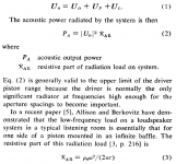
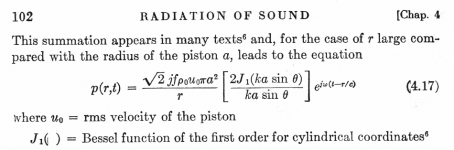
I've attached captures from Small's "Direct Radiator Loudspeaker System Analysis", and Equation 4.17 of Beranek.
In the former, Small shows the relationship between volume velocity at the piston's surface and radiated power. This leads to the result that the radiated power is proportional to |G(j*omega)|2, where G(s) is the system transfer function.
Looking at the equation from Beranek, I assume theta = 0 for the on-axis pressure, and set r = 1 meter. The quantity in square brackets involving J1(ka sin(theta)) goes to 1 as theta goes to 0. Then you find the on-axis pressure is proportional to G(s).
Attachments
I was originally refeering to karagiosis's post. It seems like you're getting the results you are expecting, so that's good.
I'm modeling the SPL response. I don't follow what you're saying about there being a difference. When making the low-frequency approximation of the T/S analysis, they have the same frequency dependence.
I've attached captures from Small's "Direct Radiator Loudspeaker System Analysis", and Equation 4.17 of Beranek.
In the former, Small shows the relationship between volume velocity at the piston's surface and radiated power. This leads to the result that the radiated power is proportional to |G(j*omega)|2, where G(s) is the system transfer function.
Looking at the equation from Beranek, I assume theta = 0 for the on-axis pressure, and set r = 1 meter. The quantity in square brackets involving J1(ka sin(theta)) goes to 1 as theta goes to 0. Then you find the on-axis pressure is proportional to G(s).
I've been looking at the same thing with a future closed-box subwoofer design in mind and I agree - it's a mess. I've been using three software tools to investigate this.
I have a reference (Benson) who shows calculated responses with inductance and they are nowhere near as drastic as your titanic example. Sadly he doesn't develop the analytic equations (although he tells you how) just presents graphs. He uses a straight inductance, for academic reasons, and you appear to be using an inductance with a resistor in parallel so it wouldn't necessarily apply to your situation anyway. I think you need to add another series inductor to that pair, in series with Re. I usually think of them as Re, Le, Lp and Rp, the "p" indicating the parallel connection.
You are also missing leakage in your closed box SapWin model. A vented box just adds another mass and resistance and stacked transformers (one for each side of the cone) unless you want to model the higher order port resonances.
Once you have leakage and a series inductance you don't really have a second order system anymore anyway, although you can still shift the poles. You apparently have more facility than I on these control theory concepts. I'm just regurgitating some data for you to ponder on.
I have a reference (Benson) who shows calculated responses with inductance and they are nowhere near as drastic as your titanic example.
Hi Ron,
I've been looking at this some more, and the impact of LE on the closed-box system transfer function varies considerably with different drivers. I tried this analysis with a Shiva-X, which has LE=0.9 mH as opposed to the 3.3 mH of the Titanic.
When adding the series inductance, the shift in the undamped resonant frequency of the complex pole pair of the closed-box system with a Shiva-X ended up being a little less than 3.9 percent, as opposed to the 34.1 percent shift for the Titanic. I was really amazed at the difference there.
- Status
- This old topic is closed. If you want to reopen this topic, contact a moderator using the "Report Post" button.
- Home
- Loudspeakers
- Subwoofers
- Voice coil inductance effect