jbell, are you enclosing the MCM 8 with a removable baffle or is this a TH?
It's a FLH not a TH. I think Jim found this driver not well suited for a TH box.
re: 8:1 compression ratio, id like to see a few different woofers on the same horn with a high powered sine input and see what lasts. Maybe these cheap cones which are plastic sound worse but are more durable for the high compression ratio -than the pro paper based stuff?
I wonder if you see ripples or rocking with laser interferometry on weak ones. I think b&w or kef have a nice r&d explanation of what the look at on cones.
I wonder if you see ripples or rocking with laser interferometry on weak ones. I think b&w or kef have a nice r&d explanation of what the look at on cones.
Jbell,
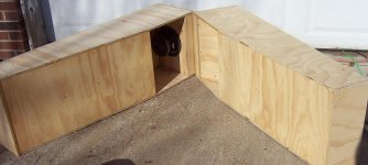
I thought you might like to see my adaptation of your bass-stick design.
I used the same MCM driver but made segment 2 and 3 slightly shorter, at 100 instead of 120. These will be used with four of the line arrays pictured. (It will result an 8 foot long line array on each side of the stage) The small change in height allows me to use the bass-stick cabinets as stands for the line-arrays in a room with 8 foot ceilings for smaller venues. I actually desired a response curve that extended upwards as I cross over at about 180Hz. I did not need response below 40Hz.
These will be used for PA use and to supply music for ballroom dancing. Their first public use will be in the ballroom at the local convention center for a black-tie formal dance. In my living room a single cabinet can easily supply enough volume. (I've been cautiously breaking in the drivers) With four cabinets I'm hoping I'll have sufficient bass to fill a gymnasium sized ballroom to 85+ dB levels.
I do not have the rear enclosure covers for the drivers in place yet to make them into true front-loaded-horns. I expect right now their frequency response is a bit ragged since their back-chamber cover is missing.
The bass-sticks easily exceeded my expectations in performance. I know what really low distortion high quality bass sounds like, as I have a pair of 18" Avalanche drivers in 12.5 cubic foot cabinets in my home theater. I did not expect an 8" driver to come close, but they really are impressive.
J. L.
An externally hosted image should be here but it was not working when we last tested it.
Hey JL, I hadn't thought about this thread for a LONG time.... I thought I'd add a bit of info for you on these so you can have success with them.
First they are designed so that by themselves, they are not a complete cabinet. They were modeled in hornresp assuming they were 'v-plated' aka, put in the below configuration and a 3/4" plywood plate bolted to the top, so that the cabinets, floor and plywood plate extend the horn length / mouth size.
For a gymnasium setup, find the middle of a concrete wall, set up the 4 cabinets in a single 'V' so that you have a mouth that is basically 32"x60" Set it up so that the mouth is facing the wall and is about 32" away from the wall. This will effectively give you something close to 1pi cabinet loading.
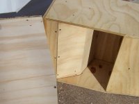
On the driver cover, yes you definitely want it, and it needs to be as small as possible. I attached a pic so you could see what I did. I basically joined a couple boards at what I thought was a reasonable angle. Then taped a piece of cardboard over the back of the magnet to set a small gap so the cover wouldn't touch the driver, set the angled board down till I thought it was appropriate, and drew a line. The cleats you need to install for the cover to attach to are obviously 1/2" below that line. Use window gasket foam to make sure it's air tight.
In terms of standing them up and putting a line array over them, I think that only works if you have corners. If you have a small enough room that you can put a line array in each of the front 2 corners, then put a bass stick under each one facing into the corner, I think that will work well as the corner will 'finish' the cabinet, ala k-horn.
BTW -- nice looking cabinets.
First they are designed so that by themselves, they are not a complete cabinet. They were modeled in hornresp assuming they were 'v-plated' aka, put in the below configuration and a 3/4" plywood plate bolted to the top, so that the cabinets, floor and plywood plate extend the horn length / mouth size.
For a gymnasium setup, find the middle of a concrete wall, set up the 4 cabinets in a single 'V' so that you have a mouth that is basically 32"x60" Set it up so that the mouth is facing the wall and is about 32" away from the wall. This will effectively give you something close to 1pi cabinet loading.
On the driver cover, yes you definitely want it, and it needs to be as small as possible. I attached a pic so you could see what I did. I basically joined a couple boards at what I thought was a reasonable angle. Then taped a piece of cardboard over the back of the magnet to set a small gap so the cover wouldn't touch the driver, set the angled board down till I thought it was appropriate, and drew a line. The cleats you need to install for the cover to attach to are obviously 1/2" below that line. Use window gasket foam to make sure it's air tight.
In terms of standing them up and putting a line array over them, I think that only works if you have corners. If you have a small enough room that you can put a line array in each of the front 2 corners, then put a bass stick under each one facing into the corner, I think that will work well as the corner will 'finish' the cabinet, ala k-horn.
BTW -- nice looking cabinets.
Attachments
I understood that when I started the project. In my own hornresp simulations I deleted the final segment of the horn to predict the response without it. (It still looks good for my intended use)Hey JL, I hadn't thought about this thread for a LONG time.... I thought I'd add a bit of info for you on these so you can have success with them.
First they are designed so that by themselves, they are not a complete cabinet. They were modeled in hornresp assuming they were 'v-plated' aka, put in the below configuration and a 3/4" plywood plate bolted to the top, so that the cabinets, floor and plywood plate extend the horn length / mouth size.
I don't know if I'll ever need to generate that kind of SPL these things are capable of when stacked and configured as you described, but if I ever need to fill a gymnasium with sound for a younger audience, it is nice to know it can. I'm not sure I would have ever thought to face the mouth to the wall, but I can see how the wall would then act as the final reflector and horn segment.
Actually, they do not do too badly as shown in my picture. The floor forms one side of the final horn, and the standing cabinets the other side at 90 degrees. The four cabinets side-by-side result in a horn width of 72 inches by 44 inches high.For a gymnasium setup, find the middle of a concrete wall, set up the 4 cabinets in a single 'V' so that you have a mouth that is basically 32"x60" Set it up so that the mouth is facing the wall and is about 32" away from the wall. This will effectively give you something close to 1pi cabinet loading.
I described the first venue I'd be using them in as gymnasium sized... Unfortunately, the wall I'm setting up against is a 20 foot high folding accordion style wall that separates their very huge ballroom into 6 smaller spaces. We'll be using two of those ballroom spaces for our dance. The folding wall is probably not a great reflector at bass frequencies. It is most definitely not concrete.
The up side is that I'm not trying to provide high SPL, in fact, the bass-sticks will probably be loafing along most of the evening. My sound equipment is being used to supplement the "house" sound system, as it has very poor bass response being designed more for speech than music.
I'm more constrained by appearance and stage placement then the need for as loud and deep and even a response as possible.
Thanks for the additional pictures and description of how you measured/fitted them.On the driver cover, yes you definitely want it, and it needs to be as small as possible. I attached a pic so you could see what I did. I basically joined a couple boards at what I thought was a reasonable angle. Then taped a piece of cardboard over the back of the magnet to set a small gap so the cover wouldn't touch the driver, set the angled board down till I thought it was appropriate, and drew a line. The cleats you need to install for the cover to attach to are obviously 1/2" below that line. Use window gasket foam to make sure it's air tight.
Thanks. A bit of stain and a coat of polyurethane makes then fairly attractive as long as you do not look too close.In terms of standing them up and putting a line array over them, I think that only works if you have corners. If you have a small enough room that you can put a line array in each of the front 2 corners, then put a bass stick under each one facing into the corner, I think that will work well as the corner will 'finish' the cabinet, ala k-horn.
BTW -- nice looking cabinets.
") It turned out my local Home Depot had the better plywood this time. It was equal to the auroco carried by Lowes down the street, with 5 equal size plys, one side cabinet grade, but on sale at $18 a sheet. Only issue is that it was 15/32 instead of 1/2 inch.
It turned out my local Home Depot had the better plywood this time. It was equal to the auroco carried by Lowes down the street, with 5 equal size plys, one side cabinet grade, but on sale at $18 a sheet. Only issue is that it was 15/32 instead of 1/2 inch.I've read posts from you were you've been hesitant to put more than 20v on them. Right now I've got one channel of a NADY 900 amplifier driving all four cabinets (wired in series/parallel to present a 4 ohm load) It can output 300 watts per channel into 4 ohms if turned up. 75 watts per driver is probably less than you've pushed them, and I've not turned it all the way up.
Believe me, it is far more than I need in my living room. My initial tests were with an amplifier that probably does not put out more than 30 watts per channel. It was pretty loud even with that.
Thanks again for a great concept.
J. L.
Last edited:
Well again -- congrats to you JL.
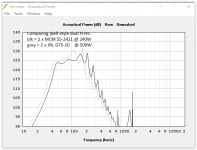
I did a quick hornresp, and for the way you are going to use them, just leave them without the cover. Looks like you are reasonably flat to 60hz, and can get about 120db@20v per cabinet. (just run a high pass at 40hz)
Putting the cover on, and making a FLH out of them only helps you if you lay them on their side and v-couple. Then you can get flat to 40hz.
Again, great job, looks like they will work well for you.
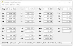
Wow... thanks for taking the time out to verify what I'm hearing. You really went out of your way. I know the response is not perfect, and I know my needs are different than yours. I did take the time to learn enough about hornresp to simulate the open rear chamber and altered segments before I started any cutting of wood. hornresp is a very nice program and I'm sure I've only touched on a small portion of its capabilities. About the only thing I've not figured out is how everybody gets all the windows open at the same time in their apparent screen captures. When I open the Edit screen the SPL window closes... There are so many posts with all the windows open at the same time. Are people just cutting and pasting into "paint" ?
As you might have guessed, the average 50 to 85 year old ballroom dancer does not expect chest pounding ear splitting bass. I have a much easier audience to please than you do when playing to high school kids in a gymnasium
Thanks so much again for your project's inspiration of mine.
J. L.
As you might have guessed, the average 50 to 85 year old ballroom dancer does not expect chest pounding ear splitting bass. I have a much easier audience to please than you do when playing to high school kids in a gymnasium
Thanks so much again for your project's inspiration of mine.
J. L.
Flip:
BTW, the 8:1 compression, no problems with 8" cones. I've had these cabinets wound up, and no issues, I'm pretty sure the small chiwaneese voice coil will melt down before I have a cone issue.
Is there an easy formula to calculate the CR? Looking at either a 15" or 18" Ultimax 3" from back of wall in a TH- 13' long x 22" high. Depth is the hard part. Need to keep it under 16". (3" deep first segment then increasing to 11" at the end plus wood is around 16" max.). Struggling with hornresp or I wouldn't ask here.
Knock knock - is this thing on?
I tried pm'ing jbell directly, but no responce.
I'm at a loss for the reason this thread went flatline.
This proposed dual 8" FHL, and it's reported Fq response would of normally caused quite the stir.
Unfortunately my life will not accommodate the time to learn Hornsrep or the akabaka (sp?). But those here who have, I believe this dual-8" design really deserves some more attention!!!
For a mobile DJ, this would be an easily packed lightweight & cost effective subwoofer option. Especially in multiples. Four units would rock, and cost quite a bit less that the 15/18's they would replace.
Hi Doc777,
Post #49: "...easy formula to calculate the CR?...Struggling with hornresp..."
You would be best of to open your own thread, and have an administrator place your Post #49 and this reply into the new thread. Either way:
CR (compression ratio) = Sd / S2
(driver effective cone area divided by the cross-sectional area of the horn (or pipe...) @ the point of entry (from driver into horn)
See attached example(s) for your TH, the .txt files are for Import into Hornresp.
Regards,
Attachments
tb46,
Since you responded to this thread and seemed to have a handel on Hornresp, I'll direct this to you.
Given the details listed earlier in this thread, could you reverse-engineer this design. What I am very interested in ( and I can't believe others aren't ), is cab dimensions for std 3/4 or 18mm ply, and maybe a simple rendering of a optimized fold.
The crazy high c/r coupled with that trinket priced 8" driver seemed to produce magic. If a (still affordable) yet better driver was sourced, it seems these cabs would be awesome.
Now I can understand why most here are not excited about this design. The two 8" collectively are rated at 250watts rms. Counter to the popular trends of gigawatt 5" inside/outside wound hexagonal oflc beryllium-copper neo magnet 21" with >50mm pp xmax & 110dB sensitivity bla-bla-bla.
According to jbell this design was producing 120dB @ 40Hz @ 200watts 2pi in what was sounding like a less than 5cube cabinet with $60 worth of drivers.
That gets me excited!
THX in advance!
Chris
FWIW I cobbled together a single TH to test the 8:1 awhile back and it was doing 110+ dB peaks/30 Hz in a simple bi-fold ~47 L/1.66 ft^3 net, so using HR to sim a 40 Hz dual driver variant, it too does 120+/40 Hz and in only ~71 L/2.51 ft^3 net, so a bit larger FLH should do at least as well and have much more mids/HF output to boot.
GM
GM
Hi Sublimacon,
There were at least two versions, the original one w/ the 1st section leaving the throat chamber @ the side (Post #12 here), and one w/ the 1st section in the middle (Post #1/13 here, and see below). Then there is the single driver version in Post #23...45.
Here is another thread on the subject:
http://www.diyaudio.com/forums/subwoofers/192075-mcm-8-55-2421-ts-parameter-5.html
see Post #41 for the version w/ the bifurcated initial horn path.
Also, see epa's design starting around Post #63 (updated plans in Post #139...155...214). Kornnylike build that one, there are pictures around Post #192....
Right now I don't have the time to work all the way through this one. But one recommendation, if you keep the overall dimensions about as indicated, and stick closely to the dimensions around the driver (especially the throat area) you should not have any problems building this from the pictures jbell has provided.
Regards,
GM & tb46,
Thanks for all the info!
~GM, that was an interesting experiment with a high c/r TH. My understanding of TH is that they typically shoot for lower cone loading (1/4 wave resonator stuff) and typically demand high xmax drivers to achieve their spl's.
Just go's to show, when the right parts are assembled sometimes the rules can be bent/broken. Now if extrapolated for dual drivers & 2x pwr, your box would do 116dB @ 30Hz 2pi per cab? Was that with an 8" - can that be correct, seems like that should be breaking thermodynamics laws! I have dual-18 ported cabs that would smoke the the vc's before measuring that!
tb46 ~ no problem on the reversed eng, I too have little free time for such things and can sympathize. I'll definitely check out that other thread - thanks. I fear you are extending far to much credit to me on figuring out jbell's fold. I've been building home & car speakers/subs/sys for over three decades, yet not a single horn design to date.
BTW, my Forum handel is not in anyway a suggestion of my god-like audio skills, rather it was a joke yahoo email account I came up with in 1994. "Sublimacon - we're programing your mind for a better tomorrow". Just some dark advertising humor of mine!
Hi Sublimacon,
Post #55: "...on the reversed eng...figuring out jbell's fold..."
I once made a sketch of the original dual driver 55-2421 FLH, but decided against pursuing the subject any further at that time. I added a few dimensions, but you'll have to work through it yourself for your wood thickness. Make sure, that the throat opening ends up to be 2"x4" that will give you jbell's compression ratio, and the 4" dimension w/ the slanted baffle will give you the first part of the horn.
Regards,
Attachments
tb46,
Thank you much for the info & steering me towards that other thread! Which BTW is almost comical, the back & forth between epa & kornny is hilarious. If Amsterdam elects poeple as saints still, epa certainly gets my vote - LOL!
On a side note, their intent of digging deeper sort of diminishes some if the magic of jbell's original. Almost doubling volume/size for a 5Hz lower f3 seems a little silly. As per my understanding of horn loading, simply multiplying cabs to virtually increase horn path would result in the same ultimate spl. Given how cheap the drivers/plywood are per cab, having 4 to 8 mini-subs would still be very viable for many DJ's / small bands.
I believe (possibly misguided) that given all the data from the larger variant, I might be able to scale it back down to the original ver, and mantain fold geometry.
THX!
Chris
Hi Sublimacon,
As the JBL GT5-10 seems to still be on sale, I decided to see if I can fit two into a close approximation of jbell's fold here. A dual 10" w/ Xmax=12mm for $39.-- ea.. It'll be a few days, but I'll let you know how it comes out. I does look promising.
Regards,
P.S.: epa does great work.
As the JBL GT5-10 seems to still be on sale, I decided to see if I can fit two into a close approximation of jbell's fold here. A dual 10" w/ Xmax=12mm for $39.-- ea.. It'll be a few days, but I'll let you know how it comes out. I does look promising.
Regards,
P.S.: epa does great work.
tb46,
I've used the classic series & various generations of GT's in auto installs. My bucket commuter car has a single GT15. Infinate baffle to the trunk, feed through a sloped plenum on the rear window deck. It's a little sloppy on the transients, but it causes >1/8" windshield flex front & rear on less than 400 watts. BTW, I've beat the crap out of that driver for years (mech-limit) and it just keeps ticking along!
So I got to admit, I'm rather curious to see the out come of your 10" experiment. In my experience the consumer JBL stuff has above average sensitivity, but not the strongest motors coupled with middle of the road Q's to work in sealed/ported/BP boxes. A compromise by design.
So with the SD of a 10" and a set of T/S not anywhere near optimized for horn loading. I'm not sure they'll be as awesome at 8:1 as the el-cheapo mcm drivers. If the OEM would of used an epoxy a little stonger than elmers-glue, they would of been golden!
I seem to remember a line of Goodwood (not a fan of that brand) that responded well to H/L, perhaps a 8" from them might be a low'ish cost upgrade from the fragile mcm's.
Post # 56
Hi Sublimacon,
After playing around w/ the GT5-10 in Hornresp it looked promising. There is not enough room for the S1 that this FLH/drive combination would require, but w/ a CR of 4.7:1 it can be made to work. This driver should be able to handle quite a bit more power than the MCM 55-2421, so that would help.
I'll attach where I'm at right now if someone is interested, or wants to build it.
Regards,
Attachments
- Status
- This old topic is closed. If you want to reopen this topic, contact a moderator using the "Report Post" button.
- Home
- Loudspeakers
- Subwoofers
- Dual MCM FLH