while you can use a th higher than two octaves from the low corner and the response is alot cleaner than hornresp suggests, its still less than ideal sound quality wise. see the impulse spectogram (ctrl+h in spl response window) to see what i mean. compare it to a closed box for giggles. just from experience, i didnt mind using my 30hz th's up to 200hz, they measured fine too, but listenening to them alone did sound slightly weird "hollow" with higher tones.
also, you set the segments to PAR, which should be quite difficult to realize. i prefer conical for the straight walls.
also, you set the segments to PAR, which should be quite difficult to realize. i prefer conical for the straight walls.
also, you set the segments to PAR, which should be quite difficult to realize. i prefer conical for the straight walls.
Hi MaVo,
Just to clarify, if a rectangular cross-section horn segment has two parallel straight walls and two non-parallel straight walls, then the actual area expansion will be parabolic not conical. It is therefore more accurate to specify Par rather than Con in this case.
Kind regards,
David
thanks ")
then i have to say, it doesnt seem to matter, since i did it wrong with several tapped horn subwoofers and didnt realize it, despite measuring alot. i guess room modes >> build accuracy, even in nearfield.
edit: let me use this opportunity to say thank you for your amazing program and your support! both has helped me so much with this hobby.
Last edited:
Hi MaVo,
With slowly flaring horn segments, the predicted responses for Con, Exp and Par expansions will be quite similar.
Thanks for the thanks.
Kind regards,
David
then i have to say, it doesnt seem to matter, since i did it wrong with several tapped horn subwoofers and didnt realize it, despite measuring alot.
With slowly flaring horn segments, the predicted responses for Con, Exp and Par expansions will be quite similar.
let me use this opportunity to say thank you for your amazing program and your support! both has helped me so much with this hobby.
Thanks for the thanks
.Kind regards,
David
Hi MaVo,
Just to clarify, if a rectangular cross-section horn segment has two parallel straight walls and two non-parallel straight walls, then the actual area expansion will be parabolic not conical. It is therefore more accurate to specify Par rather than Con in this case.
Kind regards,
David
David,
Could you please clarify why the area expansion is parabolic?
If S is the cross section area and a (constant) and b (linearly expanded) are the rectangular dimensions, then: S=a*b. If b=k*x (where k is a constant and x the horn axis) then S=a*k*x, but a*k is also a constant so it appears to me that S expands conically?
What I am missing?
Thank you,
Could you please clarify why the area expansion is parabolic?
Hi ConExp,
Sorry, my mistake - I was not thinking too clearly at the time
.It is the equivalent axisymmetric radius that has a parabolic expansion rate, not the area.
The plane cross-sectional area of an axisymmetric parabolic horn will expand conically with axial length - the same as for a rectangular horn segment having two parallel straight walls and two non-parallel straight walls. This is why I suggested using Par rather than Con.
My apologies for any confusion caused.
Kind regards,
David
The plane cross-sectional area of an axisymmetric parabolic horn will expand conically with axial length - the same as for a rectangular horn segment having two parallel straight walls and two non-parallel straight walls. This is why I suggested using Par rather than Con.
To clarify further.
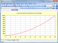
Attachment 1 shows how the plane cross-sectional area of a conical horn varies non-linearly with axial length.
S = S1 * (x ^ 2)
Where S is the area at distance x from the cone origin or vertex, and S1 is the area at distance x = 1 from the origin.
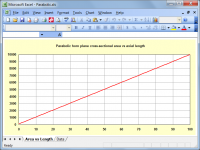
Attachment 2 shows how the plane cross-sectional area of a parabolic horn varies linearly with axial length.
S = S1 * x
Where S is the area at distance x from the parabola origin, and S1 is the area at distance x = 1 from the origin.
Kind regards,
David
Attachments
David,
my head must have got twisted back to front when I pulled on my pull-over this morning.
Could you explain that for me.
Just do the math yourself. If you have a conical expansion (think: traffic cone) the area is pi*r^2. And the radius increases linearly as you move along the cone. So if at the peak, where the radius is, say 2cm, the area is 4pi cm^2. If you move down along the cone to where it gets bigger, where the radius is 4cm, the area is already 16pi cm^2. Move down again by the exact same distance, and the radius is now 6cm, but the area is already 36pi cm^2.
As the area of your conical horn increases by a linear factor of the length in x dimesion, and in y dimension, the area increases by a multiple of this, therefor a quadratic factor of the length.
In order for the area to increase linearly, you have to decrease the rate of expansion the further out you move, in an (inverse) parabolic fashion. As hornresp simulates the horns as having circular cross sections, you need this parabolic expansion (that is: width expands with length^0.5 and height expands with length^0.5, leading to a total expansion rate constant with length^1).
Another way to achieve this expansion rate is to have one dimesion (eg height) expand linearly with the length, but keep the other dimesion constant (width of the horn stays the same). Total area expansion is then still linear. Therefore to have the same rate of area expansion for these typical horns with 2 parallel sides, you need to simulate them as Par.
David,
my head must have got twisted back to front when I pulled on my pull-over this morning.
Could you explain that for me.
Hi Andrew,
Unless I hear from you to the contrary, I will assume that James' detailed explanation has clarified things for you.
I agree that it can be a little confusing - even the late great Paul Klipsch managed to get it wrong in his classic 1941 paper when he stated that the now-famous bass corner-horn design had an initial "conical" taper. He later corrected this to "parabolic" in his follow-up 1943 paper
.Kind regards,
David
I had thought from seeing the section shape that the parabolic increased faster than the conical.
Hi Andrew,
It does - at least at the throat end
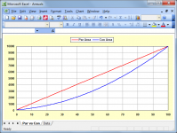
.As can be seen from the comparison below, the plane cross-sectional area near the throat of a parabolic horn (red trace) increases at a faster rate than it does for a conical horn (blue trace). The parabolic and conical horns used in the example each have S1 = 100, S2 = 10000 and L12 = 100.
Note that the chart shows horn area, not horn radius.
Kind regards,
David
Attachments
Thanks for sticking with me........... the chart shows horn area, not horn radius..........
I wonder if this is where my confusion comes from? Mistaking radius and area in plots.
The red looks like a cone to me. That suggested conical. But is actually parabolic AREA!
And "par" in the data input is not parallel but parabolic !!!
Last edited:
The red looks like a cone to me. That suggested conical. But is actually parabolic AREA!
And "par" in the data input is not parallel but parabolic !!!
Hi Andrew,
You are correct, the area expansion rate shown by the red trace is linear or "conical". The corresponding radius expansion however (which defines the horn) is parabolic. A parabolic horn therefore has a linear area expansion. Perhaps it may have been less confusing if I had used the descriptors "Area of Par Horn" and "Area of Con Horn" on my initial comparison chart, rather than "Par Area" and "Con Area".
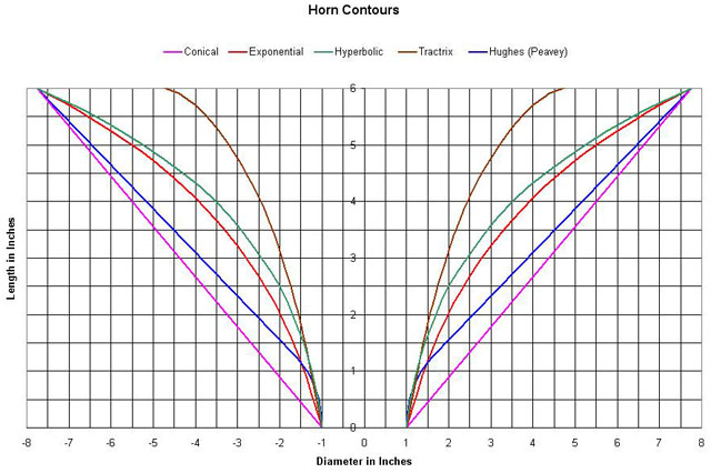
The attachment below shows the same two horns as before, but this time with the radius plotted, rather the cross-sectional area.
And yes… in Hornresp, Par means a parabolic flare horn
.Kind regards,
David
Attachments

So, I did it.
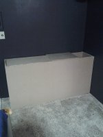
The sims with the TC Sounds Epic 12 and a 5 mh series coil looked pretty good, so I ordered 2 drivers and built two of these over the weekend. 5 sheets of MDF, 2 full tubes of PL Premium and about 2 lbs of 3 inch screws later, here they are. Figured out a fairly decent way of doing the driver access panel, which was to take some of the front panel and glue it to a larger piece that went the whole width, resulting in a cute "cap" that can be unscrewed if the driver needs to come out. Mounted the drivers this morning and somehow managed to dolly 2 of these cabinets made out of MDF down into the media room. Almost no cussing!
I've ordered a MiniDSP to go along with this. I plan to eliminate the coil once it arrives and I can bust out the microphone and dial them in properly, but let me just say, running some medium level tunes through these just to start breaking in the drivers...the output with a pair of these is nothing short of breathtaking (almost literally).
I'm bound to raise a few eyebrows at gatherings and cause a few giggles during movies.
Color me impressed.
Thanks to everyone who had a hand in the cabinet design.
Edit: A pic of my celebration toast. Cheers!
Attachments

Last edited:
I'm using the mini DSP AFTER the receiver sub output, before the amp, to run high and low pass filters on my lab 12 sub.
Only problem I see with that is adding even more delay to the LFE...I have delayed the rest of my speakers as much as possible with the onkyo receiver, but the bass is still lagging slightly. Now for movies (99.9% of what this sub is used for, it's rarely turned on when NOT watching a movie) its fine, powerful and deep. You don't really notice the delay. But with music, you can tell it sounds slightly muddy...
I'm not sure of the exact delay introduced by the mini DSP itself but I know the processing does take time....
- Home
- Loudspeakers
- Subwoofers
- Lab12 - Tapped Horn