pkgum:
Designing a servo feedback system for a subwoofer, while being relatively simple, still requires some fundamental understandings that are a little beyond a quick list of steps you need to make it work.
Also, as noted in the thread specifically relating to this topic, no company could realistically produce a servo feedback system that matched people's systems. They definitely need to be custom designed (at least if you want any decent performance from them).
what about measuring current & voltage used by the loudspeaker, and using a programmable chip to provide the correct feedback?
theoretically, the excursion should be able to be calculated if you know the current and voltage going through the speaker.
I may be wrong, this is wayyy out of my depth.
theoretically, the excursion should be able to be calculated if you know the current and voltage going through the speaker.
I may be wrong, this is wayyy out of my depth.
downhere,
While it is true that you can piece together information about a system from current and voltage or some other set of information, it is difficult. The key is an accurate math model. All sorts of bad things can happen here, like noise gets blown all out of proportion and the like. Bad things don't have to happen, but often do.
jduncan,
Really what we want is position feedback (ignoring that acoustical info could theoretically be better). To get this from an accelerometer, we need to integrate twice. This typically makes the noise situation worse. This can be overcome, but I think that some people (myself included) would like to get direct feedback on what we want to control, cutting out the middle man.
Grey,
I was asking because I teach and troubleshoot control systems in the semiconductor industry. You had piqued my intrest on this topic") I'm very curious to see what you'll come up with!
I'm very curious to see what you'll come up with!
Erik
While it is true that you can piece together information about a system from current and voltage or some other set of information, it is difficult. The key is an accurate math model. All sorts of bad things can happen here, like noise gets blown all out of proportion and the like. Bad things don't have to happen, but often do.
jduncan,
Really what we want is position feedback (ignoring that acoustical info could theoretically be better). To get this from an accelerometer, we need to integrate twice. This typically makes the noise situation worse. This can be overcome, but I think that some people (myself included) would like to get direct feedback on what we want to control, cutting out the middle man.
Grey,
I was asking because I teach and troubleshoot control systems in the semiconductor industry. You had piqued my intrest on this topic
I'm very curious to see what you'll come up with!Erik
Accelerometers can be made to be quite ridiculouly accurate. I believe ballistic missiles use accelerometers (doubly integrated) as a means of guidance for their entire trajectory. DC noise in accelerometers is rather trivially rejected, and white noise will average itself out upon integration (aka low-pass filtering).
Then there's always that observation that the integral of the integral of a sinusoid is that same sinusoid with inverse phase and some gain, so integration can be avoided entirely (I saw this in one of the accelerometer-sub articles).
The speaker driver itself "differentiates" the signal because it is essentially an inductive AC motor interacting with a mass-spring system.
Naturally, all of this must be properly modeled for an accelerometer-based subwoofer to be successful, but I believe it to be very straightforward. jduncan and I have spoken at length (off-line) about this...
-Won
"Then there's always that observation that the integral of the integral of a sinusoid is that same sinusoid with inverse phase and some gain, so integration can be avoided entirely (I saw this in one of the accelerometer-sub articles). "
The problem here, of course, is that the "some gain" varies with frequency and the superposition of the frequencies in the audio signal will not have a uniform gain you can just correct for.
This doesn't rule out compensating for this seperately in the circuit but I think it then becomes much simpler to simply do the double integration.
As also posted, this isn't incredibly difficult to do with very low noise.
Samuel,
I'd thought about the second voice coil option, but my objection to that is coupling between the two windings. If there's any significant amount of flux bleeding from the driving coil, then you're not getting an accurate measurement of what the cone is doing. That's why I brought up the possibility of an entirely separate, self-contained sensor coil.
Besides, I want something that can be done--after the fact--to any driver, anywhere, with minimal modification to the driver(s). The minimal modification stipulation tends to knock out a number of potential schemes, like epoxying a straw or magnet to the cone.
Grey
Loudspeaker feedback
If you measure the voltage over the speaker (using a diff. amp)
you will get a voltage that is proportional to the back-EMF, but this voltage is alsp an unlinear function of the cone excursion. This is due to that BL-factor decreases with increased driver excursion. If one could linearize this function, a voltage proportional to the actual cone movement could be easily measured and fed back into the amplifier.
Not an easy task...
Jacob
downhere said:what about measuring current & voltage used by the loudspeaker, and using a programmable chip to provide the correct feedback?
theoretically, the excursion should be able to be calculated if you know the current and voltage going through the speaker.
I may be wrong, this is wayyy out of my depth.
If you measure the voltage over the speaker (using a diff. amp)
you will get a voltage that is proportional to the back-EMF, but this voltage is alsp an unlinear function of the cone excursion. This is due to that BL-factor decreases with increased driver excursion. If one could linearize this function, a voltage proportional to the actual cone movement could be easily measured and fed back into the amplifier.
Not an easy task...
Jacob
philips motional feedback
Have you guys ever thought of studying the principle used in the philips motional feedback range of speakers?
a search on google will turn up many results
this one is nice to start with:
http://www.homestead.com/whaan/files/pagemfb.html
I'm guessing you're already passed this stage, so don't shoot me for giving obvious info
Hi guys - noob here. I thought sealed enc. size is pretty much dictated by the driver's specs. I understand a smaller enc. will result in a LF hump but it would probably be >100Hz right? Also my minidigi clips at serious EQ levels without any indication I don't need huge volume but do love those low low notes. I need to go DIY since shipping to me here in Ecuador is $6.50 /lb ..... ! Was thinking maybe two 15's ? I could probably go 9 cu. ft. max. Are there any programs to model two drivers? Thanks.
I don't need huge volume but do love those low low notes. I need to go DIY since shipping to me here in Ecuador is $6.50 /lb ..... ! Was thinking maybe two 15's ? I could probably go 9 cu. ft. max. Are there any programs to model two drivers? Thanks....... Are there any programs to model two drivers? Thanks.
Win Isd does it.
But 2 drivers in the same volume will have more admissible power, but no more SPL. It is better each driver with its respective box (of the same volume) if you are looking for a lot of SPL (level of the sound pressure of the sound)
Regards
Attachments
a sub doesn't need to have a lot of output at 20 Hz to be useful. There's very limited content in music or movies below about 35 Hz. Yes, you'll find a few action movies (U-571, Edge of Tomorrow, San Andreas, etc ) with significant content below 30 Hz, but it's fleeting. In music, content below 30 Hz is usually found only in a few electropop and audiophile recordings.Plus room gain is often not even thought of.
Guess you are right, I was still thinking old school Klipsch logic
( how big does a speaker have to be to reproduce a 16' organ pipe) but it's still actually been quite a while since I've listened to Bach's Tocatta & Fugue anyway. Room Gain - how big does a room have to be to provide room gain at 30 Hz ...is it one wavelength or 1/2 a wavelength - I'm just a dumb musician...
( how big does a speaker have to be to reproduce a 16' organ pipe) but it's still actually been quite a while since I've listened to Bach's Tocatta & Fugue anyway. Room Gain - how big does a room have to be to provide room gain at 30 Hz ...is it one wavelength or 1/2 a wavelength - I'm just a dumb musician...
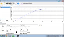
Small box, no problem. Extended bass using Linkwitz transform. From the site " 9 - 12 dB/oct highpass equalization ("Linkwitz Transform", Biquad) A majority of drivers exhibit second order highpass behavior because they consist of mechanical mass-compliance-damping systems. They are described by a pair of zeroes at the s-plane origin and a pair of complex poles with a location defined by Fs and Qt. The circuit above allows to place a pair of complex zeroes (Fz, Qz) on top of the pole pair to exactly compensate their effect. A new pair of poles (Fp, Qp) can then be placed at a lower or a higher frequency to obtain a different, more desirable frequency response.
This allows to extend the response of a closed box woofer to lower frequencies, in the above circuit example from 55 Hz to 19 Hz, provided the driver has adequate volume displacement capability and power handling. The equalizer frequency response is shown below, correcting for a woofer with peaked response (Qp = 1.21) and early roll-off (Fp = 55 Hz), to obtain a response that is 6 dB down at 19 Hz and with Q = 0.5 ."
Linkwitz Active Filters
Linkwitz Transform
Last edited:
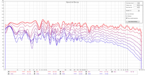
Room gain cannot be mathematically calculated for any practical case, due to many physical phenomena going on along. Sealed box systems has greatest chance to reach into infrasound without much efforts, and with lowest design / production / architectural / functional loading of the room. In the attachment there is LS1 clone in-room frequency response into 3x4meter glass fiber-insulated attic. It is hard to provide sufficient bass energy here due to lack of rigid boundaries, weak air tightness and lack of resonant room modes. There is no acoustical treatment in this room. Measurement taken with high-quality analog electret mic. Linkwitz transform set to fp=35 Hz, Q=0.7. dB scale is lifted to emulate peak power output loudness capability of playback system.
Attachments
Last edited:
Engineering is possible
Windforce85 "Room gain cannot be mathematically calculated" Well, physics and engineering, so it really can. Certainly use the room simulation function in REW to see what woofer boxes will do in your room before you start. Really cool software, and free. REW - Room EQ Wizard Room Acoustics Software
Windforce85 "Room gain cannot be mathematically calculated" Well, physics and engineering, so it really can. Certainly use the room simulation function in REW to see what woofer boxes will do in your room before you start. Really cool software, and free. REW - Room EQ Wizard Room Acoustics Software
Last edited:
Windforce85 "Room gain cannot be mathematically calculated" nailed it. Certainly use the room simulation function in REW to see what woofer boxes will do in your room before you start. Really cool software, and free. REW - Room EQ Wizard Room Acoustics Software
LOL Did you carefully read whole sentence with understanding in the context or should I return back to school to learn English?
- Status
- This old topic is closed. If you want to reopen this topic, contact a moderator using the "Report Post" button.
- Home
- Loudspeakers
- Subwoofers
- how can sealed subwoofers produce lots of low fast bass?