Where is the benefit? How does it work? DSL calls their new horns with two drivers the next generation of TH. From another forum is this quote: "This is a slight devation of the tapped horn, same concept, but with a slightly different alignment using two drivers, each feeding the horn differently."
Here is some info on the TH SPUD, one of this kind: http://forums.audioholics.com/forums/showthread.php?p=492319
Any guesses or explanations?
Here is some info on the TH SPUD, one of this kind: http://forums.audioholics.com/forums/showthread.php?p=492319
Any guesses or explanations?
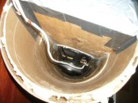
Pictures 3, and 4 appear to show Tang Band W8-740 woofers. I own quite a few of those, so I should know. Interesting that the same woofers I've used in the past have found their way into a Danley product.
http://forums.audioholics.com/forums/showpost.php?p=499616&postcount=66
http://forums.audioholics.com/forums/showpost.php?p=499616&postcount=66
"This is a slight devation of the tapped horn, same concept, but with a slightly different alignment using two drivers, each feeding the horn differently.
Pure Speculation on my part, hopefully Mr Danley will clarify:
A major goal of Pro Sound is SPL. Traditionally that means many large drivers in large boxes. They can't occupy the same physical space. The physical separation means there is less acoustic coupling, less of a point source. When drivers are separated by any distance, constructive and destructive interference takes place, until at a distance = 1/2 wavelength ( 180 degree cancellation ). Other frequencies/other wavelengths have other acoustic addition and subtraction relationships.
Delay can correct and optimize for a particular distance/frequency relationship, but it is a compromise.
Ideally get the sources closer ( in 1 enclosure ).
In my gross conceptualization of the original single driver TH, it is similar to 6th order bandpass box. With 2 driver in separate alignments, a higher order compound bandpass box.
Order?
Syd
--------------------------------------------
"If the doors of perception were cleansed every thing would appear to man as it is, infinite. For man has closed himself up, till he sees all things through narrow chinks of his cavern."
MaVo said:Where is the benefit? How does it work? DSL calls their new horns with two drivers the next generation of TH. From another forum is this quote: "This is a slight devation of the tapped horn, same concept, but with a slightly different alignment using two drivers, each feeding the horn differently."
Here is some info on the TH SPUD, one of this kind: http://forums.audioholics.com/forums/showthread.php?p=492319
Any guesses or explanations?
After reading Tom’s description more carefully, I now understand why my attempts to model the TH-SPUD failed. I took the folding diagram found here:
http://forums.audioholics.com/forums/showpost.php?p=497823&postcount=60
and blew it up and printed it on 11” X 17” paper. Then took a scaled drafting ruler to “measure” the horn lengths and calculate the areas. This is what I came up with for the various lengths and areas:
S1 = 490cm^2
S2 = 245cm^2
L12 = 21.67cm
S3 = 775.97cm^2
L23 = 497.74cm
S4 = 858.06cm^2
L34 = 92.28cm
I believe there is room for interpreting whether there is a chamber for the second woofer, or if it is a form of reverse taper. I took it as being a reverse taper. I selected L12 as the mid point between the two woofers. I did the same for L34. I now believe this is why the modeling failed. The TH-SPUD is more complicated than what it appears. I think some interesting phasing is going on to get a nice flat response. We cannot simply take the average, or mid point of the woofers and model them. I think this is like two tapped horns integrated together where the woofer offsets complement one another. A very interesting solution. I don’t think Hornresp can model it, but AkAbak should be able to.
Rgs, JLH
JLH
I'm finding similiar results in my efforts with the live cab.
The set I am building shouldn't work according to hornresp.
I tried an intentional bounce and screwing up where the phase cancellations occur at the frequencies I need to have higher spl.
I don't know what I did but it seems to work.
So to second your suspicions...
There is a lot more going on in a folded TH than meets the eye.
Re: Re: Double Driver Tapped Horn
I spent some time generating some sims from the same diagram, and came to the same set of conclusions. Hornresp isn't going to be able to model the Spud properly due to the multiple staggered path lengths. Modeling in Akabak would be interesting, but since I don't have room for a 12 cubic foot sub anyway, I probably should just resist the temptation.
What really struck me though was not that the response wasn't flat - I expected that. Rather, it's that the efficiency wasn't even close. DSL's measurements show ~97dB in half space, which is significantly higher than my model (~90), or even the dual W8 that you put together. If they had custom 2-ohm versions of the W8 then this would account for most of the difference if we assume 2.83V input rather than 1W, but I sure got the impression the numbers were for 1W.
JLH said:
The TH-SPUD is more complicated than what it appears. I think some interesting phasing is going on to get a nice flat response. We cannot simply take the average, or mid point of the woofers and model them. I think this is like two tapped horns integrated together where the woofer offsets complement one another. A very interesting solution. I don’t think Hornresp can model it, but AkAbak should be able to.
Rgs, JLH
I spent some time generating some sims from the same diagram, and came to the same set of conclusions. Hornresp isn't going to be able to model the Spud properly due to the multiple staggered path lengths. Modeling in Akabak would be interesting, but since I don't have room for a 12 cubic foot sub anyway, I probably should just resist the temptation.
What really struck me though was not that the response wasn't flat - I expected that. Rather, it's that the efficiency wasn't even close. DSL's measurements show ~97dB in half space, which is significantly higher than my model (~90), or even the dual W8 that you put together. If they had custom 2-ohm versions of the W8 then this would account for most of the difference if we assume 2.83V input rather than 1W, but I sure got the impression the numbers were for 1W.
I dont know if there are any impedance curves available on SPUD, but when i try to modell some of Danleys other designs i notice the impedance-graps are way off, and i mean _WAY off_.
Just trying to hit the same peaks and dips made some odd simulations.
There has to be more to it than meets the eye.... i wonder if the plastic tubes, wich appears in some photos, really are terminated... or if they act as an connection between frontchamber and the path.!?
Dag
Just trying to hit the same peaks and dips made some odd simulations.
There has to be more to it than meets the eye.... i wonder if the plastic tubes, wich appears in some photos, really are terminated... or if they act as an connection between frontchamber and the path.!?
Dag
At 100Hz the two drivers are well within WL/4 so are acting as one.
I've built and measured a dual driver tapped horn and didn't see any unusual behaviour I could attribute to having a pair of drivers spaced along the line. One of my tests in a 30Hz TH had the drivers 450mm apart (which was still <WL/4 for the high cutoff for the horn).
Cheers
William Cowan
I've built and measured a dual driver tapped horn and didn't see any unusual behaviour I could attribute to having a pair of drivers spaced along the line. One of my tests in a 30Hz TH had the drivers 450mm apart (which was still <WL/4 for the high cutoff for the horn).
Cheers
William Cowan
JLH said:Pictures 3, and 4 appear to show Tang Band W8-740 woofers. I own quite a few of those, so I should know. Interesting that the same woofers I've used in the past have found their way into a Danley product.
http://forums.audioholics.com/forums/showpost.php?p=499616&postcount=66
I wonder if Tom was inspired by my "Tapped Horn for Dummies" thread? The tapped horns I built use an MCM 55-2421, which is identical to the TB W8-740.
http://www.diyaudio.com/forums/showthread.php?s=&threadid=114340&perpage=25&highlight=&pagenumber=1
Tom commented on the project here:
http://www.diyaudio.com/forums/showthread.php?s=&postid=1600737&highlight=#post1600737
Attachments
Patrick Bateman said:
I wonder if Tom was inspired by my "Tapped Horn for Dummies" thread? The tapped horns I built use an MCM 55-2421, which is identical to the TB W8-740.
http://www.diyaudio.com/forums/showthread.php?s=&threadid=114340&perpage=25&highlight=&pagenumber=1
Tom commented on the project here:
http://www.diyaudio.com/forums/showthread.php?s=&postid=1600737&highlight=#post1600737
Having owned both the MCM and Tang Band I would say that is a stretch. The MCMs are marketed as being the same - but are a far cry from the quality of the Tang Band.
Rgs, JLH
JLH said:
Having owned both the MCM and Tang Band I would say that is a stretch. The MCMs are marketed as being the same - but are a far cry from the quality of the Tang Band.
Rgs, JLH
I was running one of the MCMs in a horn loaded box for a few months with over 500 watts. Never had a problem. I believe they're rated at 200 watts IIRC.
Admittedly the build quality on TB woofers is impressive, but MCM is hard to beat at the price.
Patrick Bateman said:
I was running one of the MCMs in a horn loaded box for a few months with over 500 watts. Never had a problem. I believe they're rated at 200 watts IIRC.
The enclosure type is the key to the usability of the MCM woofer. In a sealed box, horn, or tapped horn the cone motion is better controlled. After break-in, the suspension on the MCM becomes so sloppy it can't be used in a IB or bass reflex applications. You are using them right.
")
Rgs, JLH
JLH said:
The enclosure type is the key to the usability of the MCM woofer. In a sealed box, horn, or tapped horn the cone motion is better controlled. After break-in, the suspension on the MCM becomes so sloppy it can't be used in a IB or bass reflex applications. You are using them right.
Rgs, JLH
True that. I modified the QMS on a pair by adding mass to the cone, because the QTS value is so low. After modification I found I could bottom the woofer with about 25 watts, due to the increase in low frequency output after modification!
It was not the low end that increased, it was the top end you lost. You must have been feeding in more power, or your box was significantly larger to accomodate the different driver specs. If you can apply eq before the power amp, adding mass buys you nothing.
Cheers
William Cowan
Cheers
William Cowan
cowanaudio said:At 100Hz the two drivers are well within WL/4 so are acting as one.
I've built and measured a dual driver tapped horn and didn't see any unusual behaviour I could attribute to having a pair of drivers spaced along the line. One of my tests in a 30Hz TH had the drivers 450mm apart (which was still <WL/4 for the high cutoff for the horn).
Cheers
William Cowan
Hi,
Great, I actually thought so too, that two drivers, when mounted closely together, should model as ONE bigger driver
But what happens if one of the drivers is moved further up the line...to a point where they are no longer one unity...would the result be the summ of the two modelled seperately...or more complicated ?
btw, to me it seems like a TH is a design where pushpull is really working at its best, due to common loading of the horn, so that the sound at the mouth is a genuine summed output
cowanaudio said:It was not the low end that increased, it was the top end you lost. You must have been feeding in more power, or your box was significantly larger to accomodate the different driver specs. If you can apply eq before the power amp, adding mass buys you nothing.
Cheers
William Cowan
The box WAS significantly larger.
Basically every woofer has to displace a specific amount of air to create a soundwave. If you're trying to get an eight inch woofer to play to 20HZ, you're going to run out of displacement quite quickly, as the cone is a fraction of the displacement of a 12" or a 15" woofer.
Unmodified, the 55-2421 / W8 has a difficult time playing low, as it has a very low QTS value. You can augment it's output with a vented alignment, or with a horn.
But I went a different route - I went with a single reflex bandpass. To increase the output down low, I added mass to the cone. Without the added mass, I would have been forced to use a dramatically smaller box, in fact the box would have been so small the port wouldn't even fit in it!
Did I mention it's a really oddball woofer? LOL
Due to the fact that I am only getting output from the front of the cone, it's severely excursion limited. It can only handle about 25 watts.
Admittedly, that's not a lot of power. But I'm a big believer in using multiple small subs, instead of one GIANT sub.
So for my application, it works.
cowanaudio said:At 100Hz the two drivers are well within WL/4 so are acting as one.
I've built and measured a dual driver tapped horn and didn't see any unusual behaviour I could attribute to having a pair of drivers spaced along the line. One of my tests in a 30Hz TH had the drivers 450mm apart (which was still <WL/4 for the high cutoff for the horn).
Cheers
William Cowan
After some modelling in akabak, i come to the same conclusion. Theoretically, the response near the upper cutoff should be slightly different, since you have a virtually longer source that leads to a kind of spread out combfilter pattern. But this is probably not even measurable in the real world and rather theoretical. Main benefits seem to be the push pull configuration and the simple fact that you can get the double driver area into a flat horn for putting it behind a couch.
Thanks for the reality check, William.
Drivers may under heavy load and stressed conditions show slightly different behaviour when cone move in or out, which cause distortion
If I remember correctly the driver has more power moving outwards, and less inwards
Isobaric and pushpull is supposed to deal with this
Isobaric ought to be most effective, but in reality the opposite could happen
Due to difference between the two drivers theres a risk of higher distortion when under heavy load
In a pushpull where on face out and one face in, that risk may be less, due to more volume, I dont know
But still severe risk of drivers stressing each other
A sensible option could be seperate chambers fore each woofer, and is in fact occationally done so
The benefit has been disscussed and questioned, and Zaph dont believe its significant
If there is any truth in any of this, the simplest TappedHorn with just one driver facing into the throath, loading the front of cone more than the backside, could actually turn out to be the best, in terms of distortion
Maybe exactly that design is really the optimal in compensating fore driver nonlinearity
The most simple being the best...not with regards to SPL, but with quality
Is there any sense in this ?
- Status
- This old topic is closed. If you want to reopen this topic, contact a moderator using the "Report Post" button.
- Home
- Loudspeakers
- Subwoofers
- Double Driver Tapped Horn