Hi Anders,
Recognize that plot from my, or my father's that is, copy of the original RT magazine i used when building the horn!")
Unfortunately, that seas woofer is as unobtainable as many of the other referenced woofer (along with any driver parameters to compare with..
Yes, all sims I've done so far with single 10" drivers have given miserable results..
But I tried a couple of sims with two 10" woofers, and that has yielded some quite encouraging results. Especially with two two SEAS CA 26RE4X drivers, that plot even looked better than the SEAS 33F-WK!
But as these drivers are rather pricey, I'm looking for some less expensive alternatives.. iv there are any..
Recognize that plot from my, or my father's that is, copy of the original RT magazine i used when building the horn!
Unfortunately, that seas woofer is as unobtainable as many of the other referenced woofer (along with any driver parameters to compare with..
Yes, all sims I've done so far with single 10" drivers have given miserable results..
But I tried a couple of sims with two 10" woofers, and that has yielded some quite encouraging results. Especially with two two SEAS CA 26RE4X drivers, that plot even looked better than the SEAS 33F-WK!
But as these drivers are rather pricey, I'm looking for some less expensive alternatives.. iv there are any..
Anders,
You are correct in your observations regarding the orignal measurements performed outdoors. The original magazine publication does in deed state that the measurements were made outdoors with the microphone placed in the horn opening, that is just in front of the opening created by the bottom of the horn enclosure and the floor.
Obviously, this will not take in to account any room effects and the effect this might have on low frequency characteristics.
Allso, as stated earlier, the model i have "borrowed" did not include the final segment fomed by the volume below the horn enclosure and the triangular foot, as this caused an inconsistency between simulated results and "reference" measurements as performed for the original article.
From the above, it stands to reason that the simulations will never give thre true picture of the actual low end response, in particular for the very room I have my horn placed within.
However, there was a correlation between the variation of the sim result for my initial Delta-pro driver and the SEAS driver I tried and the audible results.
Based on this, I feel that I can assume that any sims indicating an improved bass response is allso likely to give an actual real life improvement.
Now for driver selection...
Some very interesting results here..
Earlier on, I mentioned a very promising simulation with two SEAS 10" woofers in tandem..
The sim showed a result superior to any other driver(s) I've tried so far (and its getting to be quite a few by now!), in terms of low end extension, Sound pressure level and smooth response.
The only drawback was the price, at around 170$ each, I'm struggling to justify the outlay for what is now effectively a experimental project..
Then I Stumbled across some cheap and cheerfull far eastern units from a brand called Sammi.
http://www.mamut.net/dynabel/subdet186.htm
Their performance was astoundingly similar to those of the SEAS units. The main difference was a somewhat reduced output as they only had an Xmax of 5,4 mm compared to the 8mm of the SEAS units.
But at 57$ each, the outlay comes far closer to something I can accept just for the sake of trying them out.
114 dB at 40 Hz and 111 dB at 35 Hz at Xmax is stil quite respectable I believe... and that's at 19,8 % and 9,07% efficiency respectively. This translates to 3,8 and 4.4 Watts, so power compression Shouldn't be an issue either..
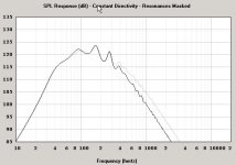
enclosed is another plot showing the curve of the Sammi drivers superimposed in grey on the SEAS 33F-WB, both at Xlim.
the only difference seems to be some improved smoothness for the sammis as well as an extended hf response (irrelevant though..)
You are correct in your observations regarding the orignal measurements performed outdoors. The original magazine publication does in deed state that the measurements were made outdoors with the microphone placed in the horn opening, that is just in front of the opening created by the bottom of the horn enclosure and the floor.
Obviously, this will not take in to account any room effects and the effect this might have on low frequency characteristics.
Allso, as stated earlier, the model i have "borrowed" did not include the final segment fomed by the volume below the horn enclosure and the triangular foot, as this caused an inconsistency between simulated results and "reference" measurements as performed for the original article.
From the above, it stands to reason that the simulations will never give thre true picture of the actual low end response, in particular for the very room I have my horn placed within.
However, there was a correlation between the variation of the sim result for my initial Delta-pro driver and the SEAS driver I tried and the audible results.
Based on this, I feel that I can assume that any sims indicating an improved bass response is allso likely to give an actual real life improvement.
Now for driver selection...
Some very interesting results here..
Earlier on, I mentioned a very promising simulation with two SEAS 10" woofers in tandem..
The sim showed a result superior to any other driver(s) I've tried so far (and its getting to be quite a few by now!), in terms of low end extension, Sound pressure level and smooth response.
The only drawback was the price, at around 170$ each, I'm struggling to justify the outlay for what is now effectively a experimental project..
Then I Stumbled across some cheap and cheerfull far eastern units from a brand called Sammi.
http://www.mamut.net/dynabel/subdet186.htm
Their performance was astoundingly similar to those of the SEAS units. The main difference was a somewhat reduced output as they only had an Xmax of 5,4 mm compared to the 8mm of the SEAS units.
But at 57$ each, the outlay comes far closer to something I can accept just for the sake of trying them out.
114 dB at 40 Hz and 111 dB at 35 Hz at Xmax is stil quite respectable I believe... and that's at 19,8 % and 9,07% efficiency respectively. This translates to 3,8 and 4.4 Watts, so power compression Shouldn't be an issue either..
enclosed is another plot showing the curve of the Sammi drivers superimposed in grey on the SEAS 33F-WB, both at Xlim.
the only difference seems to be some improved smoothness for the sammis as well as an extended hf response (irrelevant though..)
Attachments
Cool build, it looks like you've done a good job.
Note that the Klason/RT horns are similar to Tom Danley's BDEAP horns when firing at the floor. I have taken an illustration out of the BDEAP patent (see attached image) to show that the horn is larger than the bit folded in the box, or even the box and the bit underneath it. When you simulate what's in the box and put that in 1xPi, you are not modelling the entire horn.
Also, there are various ways to measure the length of a horn. When measuring the RT-2, I get something around 2.5 meters or more. I can understand assessed lengths of around 2.25 meters, but certainly not less.
The room also has a big influence on response. German diyers that have made earlier versions of the RT/Klason, mention that they needed to experiment with placement. Recommended placement is about 1/3rd down the long wall of your room and then shifting along to find a place that sounds good. Don't place it in a null or node of room resonances.
Response down to 40 Hz sounds about right for this horn, maybe with a perfect driver, adding damping material here and there and clever filtering/boosting, 30-35 Hz are possible. Especially if your room has a fitting resonance below 40 Hz.
I found this on a Swedish forum and pulled it through Google translate. This is first hand experience. There were a number of very emotional replies, saying that in the old days everything was better because you had horns like this.
Before you close it up and make something else of it, give it some more time and experimentation.
Before you close it up and make something else of it, give it some more time and experimentation.
They were the best, the light cone and fs around
50Hz. Then knallar RTE 2-hornet down to the deep 30hz
with minus 5-6dB. RT-hornet can almost be described as a subbbas-horn. The efficiency
is somewhat amazing to be as low frequencies. Using Kappa
element, under the link above, you do not believe their ears.
I also believe that the horns should be actively pursued, not necessary, but
alignment with the rest will be easier then. Think for yourself to use
200watt to the site, 2-3 watts to the base .....
Thank you for some very interesting info and feedback Ivo!
Yes, these horns seem to defy the physics, at least iv viewed in light of "conservative" and mathematically correct horn theory.
The theory presented in the schematic you posted in combination with room effects might go far towards explaining this?
Also, the schematic you provided explains a theory postulated as a basis for this horn design, that the effective mouth area would increase significantly due to reflection.
Having come over the first "shock" of the initial performance with the ill-suited Delta-pro driver, I'm seriously warming to the project again!
I believe I also did the mistake of performing initial listening and tuning at way to high levels, thereby overloading both room and ears.
The lack of distortion usually associated by exceedingly high levels could, at least, in part for this.
Now that I've listened to some records at more normal levels, it all sounds very nice.
Problem now is driver selection..
The inexpensive Sammi 10" drivers I cast my eyes on as an interesting and cost efficient alternative.. well, it turned out that the Xmax rating in the spec was somewhat ambiguous..
As a value it was given at 5,4mm, but the voice coil and gap height specified will only give 3,5mm.
I called the shop selling these drivers here in Norway, but they couldn't shed any more light on the issue, so I'll assume that 3,5 mm is the actual Xmax, not 5,4 mm.
This will reduce max SPL at full linear excursion quite a bit.. by 4 dB to be exact.
SPL @ 40Hz will now be 110dB only, compared to 117dB for the SEAS CA25RE4X, which has an Xmax of 8mm.
Allso, the guy I spoke to made me aware of the fact that the SEAS units would be down 10-12 dB in distortion compared with the Sammi's due to the superior motor design of the SEAS drivers.
I guess you get what you pay for!
110 dB SPL, cheap-driver distortion levels, very high efficiency for 120$ ?
Or 117 dB SPL, 10 dB lower distortion, slightly less efficiency for 342 $ ??
This is not easy...
On one hand, cost-efficiency allways has the appeal of getting the most for least.. On the other hand, there's the temptation to go all out for the pleasure of obtaining "the best"..
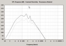
Enclosed is a plot comparing the SEAS CA 26 RE4X and Sammi
Yes, these horns seem to defy the physics, at least iv viewed in light of "conservative" and mathematically correct horn theory.
The theory presented in the schematic you posted in combination with room effects might go far towards explaining this?
Also, the schematic you provided explains a theory postulated as a basis for this horn design, that the effective mouth area would increase significantly due to reflection.
Having come over the first "shock" of the initial performance with the ill-suited Delta-pro driver, I'm seriously warming to the project again!
I believe I also did the mistake of performing initial listening and tuning at way to high levels, thereby overloading both room and ears.
The lack of distortion usually associated by exceedingly high levels could, at least, in part for this.
Now that I've listened to some records at more normal levels, it all sounds very nice.
Problem now is driver selection..
The inexpensive Sammi 10" drivers I cast my eyes on as an interesting and cost efficient alternative.. well, it turned out that the Xmax rating in the spec was somewhat ambiguous..
As a value it was given at 5,4mm, but the voice coil and gap height specified will only give 3,5mm.
I called the shop selling these drivers here in Norway, but they couldn't shed any more light on the issue, so I'll assume that 3,5 mm is the actual Xmax, not 5,4 mm.
This will reduce max SPL at full linear excursion quite a bit.. by 4 dB to be exact.
SPL @ 40Hz will now be 110dB only, compared to 117dB for the SEAS CA25RE4X, which has an Xmax of 8mm.
Allso, the guy I spoke to made me aware of the fact that the SEAS units would be down 10-12 dB in distortion compared with the Sammi's due to the superior motor design of the SEAS drivers.
I guess you get what you pay for!
110 dB SPL, cheap-driver distortion levels, very high efficiency for 120$ ?
Or 117 dB SPL, 10 dB lower distortion, slightly less efficiency for 342 $ ??
This is not easy...
On one hand, cost-efficiency allways has the appeal of getting the most for least.. On the other hand, there's the temptation to go all out for the pleasure of obtaining "the best"..
Enclosed is a plot comparing the SEAS CA 26 RE4X and Sammi
Attachments
You could try and simulate some of the Peerless XXLS
Some of them have quite nice specs and fore sub drivers they also have relatively light cones
And in some places quite fairly priced
Just remembered this quality 12" Visaton, cheap, good looks, light cone, low Fs, medium Qts, good sensitivity
Hard to find better at 85 EUR
http://www.bmm-electronics.com/Product.asp?Product_ID=1963
Attachments
Ah! Interresting suggestions!
I have allready tried sims with both peerless SLS and XXSL subwoofers, but the responses simulated were far from smooth..
Now the Visaton driver was not too bad, actually it was allmost as smooth as the SEAS 33F-WB, but both efficiency and SPL @ Xmax is in fact lower than for two Sammi 10" in tandem! being a more expensive driver, the distortion figures are probably better though..
Looking at the maximum SPL of 115 @ 40 Hz for a pair of Peerless XXSL woofers (485$) in a BR enclosure comparable with the horn in terms of volume (driven at 320W!), using two SEAS CA26RE4X drivers in the horn, which will give 117 dB @ 40 Hz is very attractive..and that's with 11,8 Watts in!
Thank you fore taking suggestions serious, makes it a pleasure
About the XXLS and sensitivity issues
The 12" with alu cone is the same sensitivity as the Visaton, it seems
But the sensitivity issue may be even much worse
The XXLS are rated at 2.85V/1m
The Visaton at 1w/1m
Dont know if you have noticed that
But then again, sensitivity is rated at a higher frequency, which as you know isnt a straight line...there could be some specific driver related frequency anormalities to consider
Well, those SPL and Xmax calculation are probably very good in telling what to expect from the design
But honestly, do you really listen at 115db SPL
I am not good at such things, but I suppose the ones showing the highest excurtions at max SPL are also going deeper, though the horn design may be a limiting factor, in which case it could seem like the ones with very low Fs maybe should be avoided
Still those are mostly the ones with good Xmax, which is also nice
Now, suddenly I begin to think in the direction of "automotive"...plenty of those around
No specs on this nice looking 12" Nova/Gradient, but 15mm Xmax(p-p) is ok
http://www.bmm-electronics.com/Product.asp?Product_ID=6002
This 12" Hivi could be one to consider, nice thick 10mm poleplate
http://www.bmm-electronics.com/Product.asp?Product_ID=6975
http://www.bmm-electronics.com/Product.asp?Product_ID=6002
This 12" Hivi could be one to consider, nice thick 10mm poleplate
http://www.bmm-electronics.com/Product.asp?Product_ID=6975
Ah.. same problem with the suggested drivers above.. seems that high Mms and low Vas does not agree with my horn..
Such parameters also seem to be a common denominator of car-type woofers as they are generally designed for working in relatively small enclosures.
And no, I don't listen to music at 115 dB, guess few does, at least for very long!
But there is a thought behind it; headroom.
Having good dynamic headroom allows for more equalisation, and a system operating well within Xmax is allso likely to give less distortion.
And then there is the less rational desire for "knowing that you can", having a sports car doesn't necessarily mean that you drive at 220 km/t all the time...
But having some in "reserve" is also attractive considering future home theater use or perhaps a larger living-room that needs proper coverage..
rated sensitivity figures are always some sort of average value, so I only judge this from simulations in with the intended application and frequency range..
And Anders, such a shame you don't have your horn any longer, if I understand right, you have some sort of measurement capability.
Some measurements to back up simulations and subjective listening impressions would have been great!
Well GM, the HR representation I'm using currently is based on something I picked up following a link earlier in this thread.
As discussed earlier in this thread, it is probably doesn't represent the full picture, but based on my experience with two different drivers so far, there seems to at least be a correlation I can use to evaluate possible driver alternatives.
As discussed earlier in this thread, it is probably doesn't represent the full picture, but based on my experience with two different drivers so far, there seems to at least be a correlation I can use to evaluate possible driver alternatives.
Elbert said:
And Anders, such a shame you don't have your horn any longer, if I understand right, you have some sort of measurement capability.
Some measurements to back up simulations and subjective listening impressions would have been great!
Elbert,
I have Clio measurement system, old today but works great.
You should arrange some measurement capabilities, you can use a PC, freeware software and a decent mike and get good results.
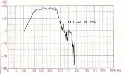
GM,
JBL 2202 graph for comparison with the SEAS 30FA graph I posted earlier:
Attachments
Anders,
A measurement set-up with some decent software and a laptop/ PC is a great idea, and something I'd definitively consider!
My only concern is obtaining a decent microphone and microphone amp that i can hook up to a computer..
Proper measuring microphones tend to be rather expensive..
but then again.. this is something I really haven't looked in to since ..well, perhaps since Clio was new and expensive!
Ivo said:Hi GM,
100 Hz Fs? Really?
Greets!
Yes, it yielded the most, best overall gain BW based on this layout: http://www.kensonpro.com/linnaraudio/linnar_simuleringar/RT2-hornet/simulering.htm
GM
4fun said:
GM,
JBL 2202 graph for comparison with the SEAS 30FA graph I posted earlier:
Greets!
I've seen two different horn layouts and neither were remotely like the measurements shown for the 2202's specs even when corner loaded, so inputted the listed throat, mouth areas, axial length, Vrc value and let HR pick the driver figuring that the existing horn could be reshaped with new inner baffles to approximate it 'close enough'. Unfortunately, I carelessly lost my sims and don't remember all the details now. IIRC it calc'd a 99.06 Hz Fs. Makes sense though since the closed chamber should be tuned to ~126 Hz for a usable 40-400 Hz compression horn.
Otherwise, a high Q, low Vas driver is better IIRC, so wondered if a high output impedance amp/whatever was used on the original to overcome the apparently too strong motor of the 2202.
GM
- Status
- This old topic is closed. If you want to reopen this topic, contact a moderator using the "Report Post" button.
- Home
- Loudspeakers
- Subwoofers
- RT-2 Horn sub, the result