john k... said:Since a few, many or all of you may doubt the results I posted for impulse response based on a simulated in room woofer response I though I would make a measurement of a woofer in my room and use that response as the basis.
...
...
Question: how did you do the min phase eq? It looks VERY precise. Did you use an iterative algorithm (Levinson-Durbin or similar?)
I see your measurement, and presumable EQ goes down to 5 HZ. What is your noise floor?
Your plot also goes up to 1 kHZ. Are eq'ing all of that. If so, there would be no argument that that is motly non minimum phase up there. Also the same question about noise at 1 kHz.
cap'n todd said:
.... (at least in the minimum phase sense, which I contend is more true than not).
Have you looked at the data I posted above? I am sure I can find a position where the response may be more MP than not, just by moving the mic close enough to the source. But I think the converse is true. The response in a room is more likely to be non-MP than MP. At least that is what both my measurement and simulations show.
I don't know if this is perhaps wht you did, but if more excess phase is removed it is possible to get something that starts to look like MP at low frequency. However, when I do this I end up removing more delay that the time of flight from source to mic. So that can not represent a physical system. It might look like MP at low frequency but it is non-causal, therefore non-MP. It implies that the sound arrived at the mic before the source produced it.
cap'n todd said:
Question: how did you do the min phase eq? It looks VERY precise. Did you use an iterative algorithm (Levinson-Durbin or similar?)
I see your measurement, and presumable EQ goes down to 5 HZ. What is your noise floor?
Your plot also goes up to 1 kHZ. Are eq'ing all of that. If so, there would be no argument that that is motly non minimum phase up there. Also the same question about noise at 1 kHz.
Noise is about 3 dividions up frm the bottom of the plot over most of thr range. Down at 5 Hz I'm having a good day and I'm up about another 5 dB (one division).
The MP cals are done using SoundEasy. I am not sure of the exact implimentation other than it follows the integral approach you can find in Bodes original text. I have written my on MP routines and find SE to be highly refined in this regard.
I'm open to suggestions, but I don't see that anything would change the phase response in the pass band where it shows several wraps, and seems consistent with my room simulations.
[edit] actually here is a plot showing the noise level. Better than I thought.
An externally hosted image should be here but it was not working when we last tested it.
john k... said:
Noise is about 3 dividions up frm the bottom of the plot over most of thr range. Down at 5 Hz I'm having a good day and I'm up about another 5 dB (one division).
The MP cals are done using SoundEasy. I am not sure of the exact implimentation other than it follows the integral approach you can find in Bodes original text. I have written my on MP routines and find SE to be highly refined in this regard.
I'm open to suggestions, but I don't see that anything would change the phase response in the pass band where it shows several wraps, and seems consistent with my room simulations.
[edit] actually here is a plot showing the noise level. Better than I thought.
An externally hosted image should be here but it was not working when we last tested it.
OK, your s/n looks good. Just thought I'd check since bad s/n can do wierd things to phase.
The method you use for inversion may have an impact here as well (pole/zero approximation in system modeling). Further there are a number of reasons why dereverberation in a real room does not alway work as expected. John Mourjopoulos has done some research on this ("Errors in Real-Time Room Acoustics Dereverberation"J. Audio Eng. Soc., Vol. 52, No. 9, 2004 September), and concluded:
Specifically it was found that under practical real-time
conditions such “high-Q” ringing poles are extremely sensitive
to small variations in the system (room) properties,
which can occur between response measurements and dereverberation tests even if the source/receiver positions and
equipment settings remain identical, so that any such test
will suffer from significant mismatch error. Hence from
this point of view the room may be considered a “weakly
nonstationary system.”
I'm sure we could argue this one for years to come, but my main point is...
Try this on for size: Look at your impulse response, and tell me at what frequency it is strongly ringing after MP EQ?? Looks like around 40 Hz. now look at your mag and phase plots. Where is the biggest cancellation dip (and phase wrap)? 40 Hz. My theory is that when you do this type of eq, namely trying to boost dips as well as redcing peaks, your end up boosting the response at frequencies where it IS non-min phase. Yes, you are also reducing the level at frequencies where (I contend) it tends to be minimum phase, i.e. the peaks. So, you could argue that the initial response was more non MP than MP, since when you flattened it, boosting the dips exacerbated the ringing more than flattening the peaks reduced it. Maybe - more analaysis of different locations and rooms would be needed perhaps to answer that. BUT, my main point is that if you EQ in a sensible way, i.e. just bring the largest peaks down to a reasonable level, you should reduce the overall ringing.
This is why I content that the responses are mostly non MP. Technically they are not MP, but effectively are with respect to (sensible) MP equalization.
I should like to see the result of a more "gentle" type of EQ in either your simulation or measurements.
Respectfully,
Todd Welti
Personally, I don't see any of this really being significant to the issue of using multiple subs and how to set those up. It never comes up any time I do multiple subs and my results always come out fine. In fact most people suggest the bass in my room is the best that they have heard - MP or not. I should mention that I DON'T use any EQ at all.
John - a boundary condition is only inhomogeneous if the pressure or the presure gradient is zero or the ratio of the two is specified. If the velocity is specified to be non-zero (independent of the pressure) on any portion of the surface then its not the an inhomogenious boundary condition. Since g(r) does not have zero velocity on the boundary no solution of the inhomogeneous boundary can cancel it there.
John - a boundary condition is only inhomogeneous if the pressure or the presure gradient is zero or the ratio of the two is specified. If the velocity is specified to be non-zero (independent of the pressure) on any portion of the surface then its not the an inhomogenious boundary condition. Since g(r) does not have zero velocity on the boundary no solution of the inhomogeneous boundary can cancel it there.
cap'n todd said:High resolution in time or frequency? No, I just meant visually, because of hte projection angle. Like if you look at someones nose from 45 degrees its harder to see how long it is compared to from the side.
Do you know FuzzMeasure ? There you can rotate a waterfall diagram freely in 3D space with your mouse.
Originally posted by cap'n todd if you EQ in a sensible way, i.e. just bring the largest peaks down to a reasonable level, you should reduce the overall ringing.
Have you found the waterfall data you were talking about that supports this?
Best, Markus
gedlee said:Personally, I don't see any of this really being significant to the issue of using multiple subs and how to set those up. It never comes up any time I do multiple subs and my results always come out fine. In fact most people suggest the bass in my room is the best that they have heard - MP or not. I should mention that I DON'T use any EQ at all.
John - a boundary condition is only inhomogeneous if the pressure or the presure gradient is zero or the ratio of the two is specified. If the velocity is specified to be non-zero (independent of the pressure) on any portion of the surface then its not the an inhomogenious boundary condition. Since g(r) does not have zero velocity on the boundary no solution of the inhomogeneous boundary can cancel it there.
I guess we are just arguing words again Earl. Seems we always end up there.
") It would seem we agree that, in simple terms, X must satisfy the wave equation with no sources in the interior and boundary conditions as required so that when added to g, it forms G, the solution for the bounded region. See, I said that without anything about homogeneity.
It would seem we agree that, in simple terms, X must satisfy the wave equation with no sources in the interior and boundary conditions as required so that when added to g, it forms G, the solution for the bounded region. See, I said that without anything about homogeneity.markus76 said:
Do you know FuzzMeasure ? There you can rotate a waterfall diagram freely in 3D space with your mouse.
Have you found the waterfall data you were talking about that supports this?
Best, Markus
The problem is that if you rotate it to the side so you can clearly see the decay, it may be blocked by other resonances in the waterfall. If you view from the side and take a "slice" you could easily see it, but then its not really a waterfall. Of course, with a 3-d cursor you can get the data easily.
I have the data, from one of Floyd's powerpoints. Not sure how to get the image inline in this message. Do i have to host the file (http://) somewhere?
It does show the mode decaying quite fast, and then at a lower rate (harder to tell at that point since it is close in level to the rest of the decay). The initial level is close to the unequalized, with a very quick early decay. Of course, the eq filter is kprobably not perfectly matched to the resonance (it is real world). Personally, I have my reservations about waterfall plots.
john k... said:
I guess we are just arguing words again Earl. Seems we always end up there.
John
But X(r) must have sources (or sinks) on the boundary otherwise when it is added to g(r) it will not yield the boundary condition since g(r) is not zero on the boundary. See I can also refute you without using that term either. We agree that there can be such an X(r), but I don't think that we see it as the same function and I don't think that it would be easy to derive. I know that I 've never seen it.
cap'n todd said:Not sure how to get the image inline in this message. Do i have to host the file (http://) somewhere?
You can attach a file with every message you compose or upload the image to a provider like http://imageshack.us/ and paste the code you get after uploading the image in your message. Alternatively you can link a file that is already online by pasting its URL in your message.
Best, Markus
cap'n todd said:
OK, your s/n looks good. Just thought I'd check since bad s/n can do wierd things to phase.
The method you use for inversion may have an impact here as well (pole/zero approximation in system modeling). Further there are a number of reasons why dereverberation in a real room does not alway work as expected. John Mourjopoulos has done some research on this ("Errors in Real-Time Room Acoustics Dereverberation"J. Audio Eng. Soc., Vol. 52, No. 9, 2004 September), and concluded:
Specifically it was found that under practical real-time
conditions such “high-Q” ringing poles are extremely sensitive
to small variations in the system (room) properties,
which can occur between response measurements and dereverberation tests even if the source/receiver positions and
equipment settings remain identical, so that any such test
will suffer from significant mismatch error. Hence from
this point of view the room may be considered a “weakly
nonstationary system.”
I'm sure we could argue this one for years to come, but my main point is...
Try this on for size: Look at your impulse response, and tell me at what frequency it is strongly ringing after MP EQ?? Looks like around 40 Hz. now look at your mag and phase plots. Where is the biggest cancellation dip (and phase wrap)? 40 Hz. My theory is that when you do this type of eq, namely trying to boost dips as well as redcing peaks, your end up boosting the response at frequencies where it IS non-min phase. Yes, you are also reducing the level at frequencies where (I contend) it tends to be minimum phase, i.e. the peaks. So, you could argue that the initial response was more non MP than MP, since when you flattened it, boosting the dips exacerbated the ringing more than flattening the peaks reduced it. Maybe - more analaysis of different locations and rooms would be needed perhaps to answer that. BUT, my main point is that if you EQ in a sensible way, i.e. just bring the largest peaks down to a reasonable level, you should reduce the overall ringing.
This is why I content that the responses are mostly non MP. Technically they are not MP, but effectively are with respect to (sensible) MP equalization.
I should like to see the result of a more "gentle" type of EQ in either your simulation or measurements.
Respectfully,
Todd Welti
Hi Todd,
I totally agree with you that trying to eq the dips is why the eq'ed impulse resoponse is worse that the raw response. And just cutting the peaks can make things better but still not correct. Cutting the peak will usually make things better, even if not MP(but not always if not MP), because you are reducing energy in the system. Boosting the dip is a double edged soword. If the response were MP then it would help because it would be removing a resonance (a MP response dip rings just as much as a MP boost but with inverted phase).
I'm still of the belief that getting the response to behave as MP
That is why I think the approach has to be to make the response MP, and then worry about eq.
markus76 said:
You can attach a file with every message you compose or upload the image to a provider like http://imageshack.us/ and paste the code you get after uploading the image in your message. Alternatively you can link a file that is already online by pasting its URL in your message.
Best, Markus
ok, here's one. I have found another I can upload if you are interested.
Attachments
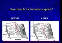
Thanks Todd, I was hoping that you will post that particular CSD because it's the same Toole used in his book What we see is that the ringing is attenuated (which is good) but at the same time the decay rate has become slower (which is bad). In a minimum phase system the decay rate should be faster after applying an EQ, right?
Best, Markus
What we see is that the ringing is attenuated (which is good) but at the same time the decay rate has become slower (which is bad). In a minimum phase system the decay rate should be faster after applying an EQ, right?Best, Markus
gedlee said:
John
But X(r) must have sources (or sinks) on the boundary otherwise when it is added to g(r) it will not yield the boundary condition since g(r) is not zero on the boundary. See I can also refute you without using that term either. We agree that there can be such an X(r), but I don't think that we see it as the same function and I don't think that it would be easy to derive. I know that I 've never seen it.
Earl you missinterpreted what I posted, due to my poor gramar.
It would seem we agree that, in simple terms, X must satisfy the wave equation with no sources in the interior and boundary conditions as required so that when added to g, it forms G, the solution for the bounded region.
How about if I rewrote that as, "In simple terms, X must satisfy the wave equation with no sources in the interior. Boundary conditions as required are applied so that when added to g, g + X = G, the solution for the bounded region."
I would agree that solving the wave equation, with appropriate boundary conditions, for X might not be an easy task, but someone must have done it to come up with the modal expansion for G. So, X = G-g must at least be a reasonable representation of X, at least as good as G is a representation of the bounded region Green's function.
markus76 said:Thanks Todd, I was hoping that you will post that particular CSD because it's the same Toole used in his book
Best, Markus
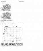
I dont think the decay rate is slower. It is certainly much faster in the early part. So overall if you avoid noise floor, I think the decay is faster. Here's more from Karjalainen et al, which shows the "slice" of the waterfall for the resonance in question. Similar to the Toole plot, the decay is much faster at the start and slower later. One reason for this is the noise floor, which I'm sure is right about -25 dB. So, the effect on the decay would start around -15 dB. The other thing, and perhaps this is what you are referring to, is that this type of decay may happen when the Q of the filter does not match the resonance exactly. i may have more on this, if I can find it... . keep in mind that in this example ther're not even trying to remove the resonance, just bring it down to the level of nearby peaks.
Attachments
john k... said:
Hi Todd,
I totally agree with you that trying to eq the dips is why the eq'ed impulse resoponse is worse that the raw response. And just cutting the peaks can make things better but still not correct. Cutting the peak will usually make things better, even if not MP(but not always if not MP), because you are reducing energy in the system. Boosting the dip is a double edged soword. If the response were MP then it would help because it would be removing a resonance (a MP response dip rings just as much as a MP boost but with inverted phase).
I'm still of the belief that getting the response to behave as MP
That is why I think the approach has to be to make the response MP, and then worry about eq.
Hi John, so are you trying to remove all ringing then? Then add some back in to make it sound more natural? I'm dont really think its necessary, but sounds interesting.
cap'n todd said:So overall if you avoid noise floor, I think the decay is faster.
At least it's not clear and that's all I was talking about.
Up to what frequency would you recommend the use of an EQ?
Best, Markus
markus76 said:Thanks Todd, I was hoping that you will post that particular CSD because it's the same Toole used in his book
Markus, I think you mean that the decay RATE should be similar in an approximately minimum phase system, but the decay TIME should be faster because the starting amplitude is lower. You had previously substituted one term for the other many pages ago, and it makes discussion a little confusing. It's hard to make out the slope here, but you can see that the resonant frequency hump goes to zero earlier AFTER equalization, hence the decay TIME is in fact faster.
markus76 said:
At least it's not clear and that's all I was talking about.
Up to what frequency would you recommend the use of an EQ?
Best, Markus
IMHO
A few hundred Hz for sure, higher than that is another question.
youngho said:
Markus, I think you mean that the decay RATE should be similar in an approximately minimum phase system, but the decay TIME should be faster because the starting amplitude is lower. You had previously substituted one term for the other many pages ago, and it makes discussion a little confusing. It's hard to make out the slope here, but you can see that the resonant frequency hump goes to zero earlier AFTER equalization, hence the decay TIME is in fact faster.
Isn't this elementary linear systems theory? If you reduce the Q of a MP resonance, the time constant (i.e. decay rate) is reduced.
time const = Q/(pi*Fo) or somehting like that.
Again, I think that at least part of the complication here is that the Q of the correction filter seldom exactly matches the resonance. In fact it may not always be easy to determine the Q of the resonance. So you end up with a corrected response that has two slopes, from the Q of the resonance and the correction filter not cancelling correctly. Should it be surprising that the decay in time has two slopes then?
- Home
- Loudspeakers
- Subwoofers
- Multiple Small Subs - Geddes Approach