Post #582
Hi MikeHunt79,
Sreamerusa has documented his design in:
http://www.screamersusa.com/furybox.html
and the transfer page has his Hornresp Input screen.
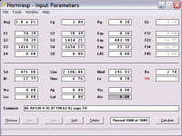
In Post #530 I added my 2 cents with a drawing, and in Post #534 screamerusa pointed out the angles of the internal reflectors. This led to the updated drawing in Post #535 which also contains the Hornresp input values in tabluar form.
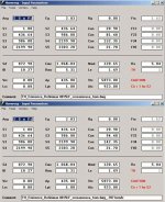
I'll attach my Hornresp Input screens for Post #579's SPL curves. As to the Ciare 15.00SW: it looks like a very fine speaker. It would be nice to hear the input of some of our PA-Pros on that subject.
Regards,
Hi MikeHunt79,
Sreamerusa has documented his design in:
http://www.screamersusa.com/furybox.html
and the transfer page has his Hornresp Input screen.
In Post #530 I added my 2 cents with a drawing, and in Post #534 screamerusa pointed out the angles of the internal reflectors. This led to the updated drawing in Post #535 which also contains the Hornresp input values in tabluar form.
I'll attach my Hornresp Input screens for Post #579's SPL curves. As to the Ciare 15.00SW: it looks like a very fine speaker. It would be nice to hear the input of some of our PA-Pros on that subject.
Regards,
Attachments
Re: Posts #519 / #529
tb46, thanks! I only just noticed your reply by chance I think I may have to do trial runs.
  At least the driver's sorta versatile. Do you have an example fold for the L23=L34 design?
My maths brain is broken.... is there a more specific way to work this out? I only have three data points, S2,S3 and S4.
tb46 said:Hi fb,
Here is another take on building a tapped horn for the AV12H to your specs in Post #519. This one models well CON and EXP. Seeing the difference in response between screamerusa's measured results and the Hornresp model, I'd use OSB for a trial run.
Regards,
tb46, thanks! I only just noticed your reply by chance
I think I may have to do trial runs. At least the driver's sorta versatile. Do you have an example fold for the L23=L34 design?fb said:
Is y = e^x the form of the equation to calculate the area at a given distance along the path?
My maths brain is broken.... is there a more specific way to work this out? I only have three data points, S2,S3 and S4.
Well, the math is beyond me and why I use a proprietary Excel SS someone designed for me, but you can use an on-line Java applet such as this one.
Input S1 in the 'throat' box, input the flare frequency from F12, etc. except ignore any marked '0'. If you choose to use more than one flare frequency, then you'll have to plot each one individually. M = 1 since HR only does pure exponential flares in TH mode whereas the more appropriate flare factor would be a much lower hyperbolic/exponential one, hence a lot slower expansion (longer) for a given throat/mouth area. cab width would normally be the SQRT of the mouth area to make it square, but then the throat area would have a high aspect ratio which may be either a plus, minus or neutral condition in a TH, but I've no experience yet, so Caveat Emptor. For sure, the high aspect ratio mouth that a square throat yields will affect its HF performance, controlling its output like any other slot mouth, so unless someone proves otherwise, having some extra acoustic resistance back at the throat due to a high aspect ratio seems like a plus to me.
GM
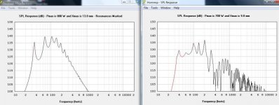
GM said:Hmm, didn't think about the EXPORT function, but when I went to test it using the expo sim I did for fb, I couldn't get it to work.
GM
Works for me. Did you add the first line? (Horn resp doesn't include it.)
Akabak is tricky, but the export function from Hornresp makes it a heck of a lot easier.
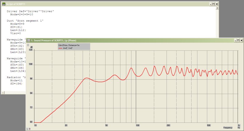
System 'S1'
|DATA EXPORTED FROM HORNRESP - RESONANCES NOT MASKED
|COMMENT: AE AV12H-4 16.97-184.62 expo TH
|========================================================================================================
|REQUIRED AKABAK SETTINGS:
|File > Preferences > Physical system constants:
|Sound velocity c = 344m/s
|Medium density rho = 1.205kg/m3
|Sum > Acoustic power:
|Frequency range = 10Hz to 20kHz
|Points = 533
|Input voltage = 2.00V rms
|Integration = 2Pi-sr
|Integration steps = 1 degree ... 1 degree
|Integration method = Cross
|========================================================================================================
Def_Const |Hornresp Input Parameter Values
{
|Length, area and volume values converted to metres, square metres and cubic metres:
Rg = 0.10e-0; |Amplifier output resistance (ohms)
S1 = 70.39e-4; |Horn segment 1 throat area (sq cm)
S2 = 70.39e-4; |Horn segment 1 mouth area and horn segment 2 throat area (sq cm)
S3 = 1414.21e-4; |Horn segment 2 mouth area and horn segment 3 throat area (sq cm)
S4 = 1634.17e-4; |Horn segment 3 mouth area (sq cm)
L12 = 0.10e-2; |Horn segment 1 axial length (cm)
L23 = 483.98e-2; |Horn segment 2 axial length (cm)
L34 = 23.32e-2; |Horn segment 3 axial length (cm)
|Parameter Conversions:
Sd = 471.00e-4; |Diaphragm area (sq cm)
}
|========================================================================================================
|Network node numbers for this tapped horn system:
|0-Voltage-1-Resistance-2
| |
| -Driver--
| | |
| 8-Segment-9-Segment-10-Segment-11-Radiator
|========================================================================================================
Def_Driver 'Driver'
Sd=471.00cm2
Bl=17.77Tm
Cms=2.18E-04m/N
Rms=6.76Ns/m
fs=24.0001Hz |Mmd = 195.83g not recognised by AkAbak, fs calculated and used instead
Le=0.28mH
Re=2.70ohm
ExpoLe=1
System 'System'
Resistor 'Amplifier Rg'
Node=1=2
R={Rg}
Driver Def='Driver''Driver'
Node=2=0=9=10
Duct 'Horn segment 1'
Node=8=9
SD={S1}
Len={L12}
Visc=0
Waveguide 'Horn segment 2'
Node=9=10
STh={S2}
SMo={S3}
Len={L23}
Waveguide 'Horn segment 3'
Node=10=11
STh={S3}
SMo={S4}
Len={L34}
Radiator 'Horn mouth'
Node=11
SD={S4}
Hornresp_Schematic_Export
Hi GM,
I just tried it again and the export function seems to work.
Let's see, in the Schematic window: File, Export, then from the right: I'm entering Uni under Width Flare, increments that match with inches (0.079/2.54/2.54/0.635), leave the Width alone, and set all the Height inputs to one value (e.g.: 35). Hit OK. Click csv button. Type in a name (up to 8 characters only), and hit save. The file is stored in the C:\Hornresp\Export folder. Open file with Quattro Pro (or your favorite spreadsheet), and everything looks fine.
Well, I have to run, may not be back until June.
Regards,
Hornresp_Schematic_Export
Hi GM,
I could not duplicate your problems, sorry, but your simulation worked just fine for me. This time I made no changes, just Export - OK - click on csv button - name - hit save.
Well, back to packing for the trip.
Regards,
P.S.: The attached file is a .csv file as this is not an allowed file type I changed it to txt - just change it back to .csv.
Attachments
Greets!
OK, since the TH has an expo flare, it's what I was trying as well as the 'uni', but it works fine for me using 'con' also. Anyway, after much fiddling with other sims with no problems I wondered if somehow my sim was 'different, so deleted /re-inputted it, but that didn't help either. Setting 'S2' to 'con' and the others to either 'expo' or 'uni' did work though. Weird.
Anyway, thanks for the effort and hope you have a safe trip/pleasant holiday. Rain's in the forecast for us.
GM
P.S.: Interesting, I didn't know you could do that. Thanks!
Patrick Bateman said:
Works for me. Did you add the first line? (Horn resp doesn't include it.)
Akabak is tricky, but the export function from Hornresp makes it a heck of a lot easier.
Thanks for the info/AkAbak scripts you've been pumping out. I imagine I'm going to need all the examples I can find once I take the time to learn it.
GM
screamersusa,
I have not figured out how to reply to a specific post on this forum, so apologize if my post is out of sequence.
The Eminence 4015 is rated at XMax of 9 mm, XLim 15.5, the one unit I have seems to audibly change character @ 11 mm peak to peak,(big time harmonics) and clacks at 16mm P to P, obviously X mech/lim.
That would seem to indicate that either my 4015LF was built wrong, or the Xmax/XLim specifications are incorrect, like they are written for peak to peak instead of one way as they should be.
The factory may have mounted the coil too far back on this unit, but it performs well in a ported cabinet, so that seems unlikely.
My eight Eminence LAB 12 measure like the published specs for Xmax and Xlim, though about 36 mm P to P is as far as I have pushed them.
I was wondering if you (or any others) have measured the actual excursion of the 4015LF at any specific drive levels or frequencies?
I have not figured out how to reply to a specific post on this forum, so apologize if my post is out of sequence.
Post #566
The original test cab was a 3015. I am using both 3015LF and 4015 at the moment. The 4015 seems a little lighter on the low end but it sounds a little better to me than the 3015LF. The 3015 provides more low end.
The Eminence 4015 is rated at XMax of 9 mm, XLim 15.5, the one unit I have seems to audibly change character @ 11 mm peak to peak,(big time harmonics) and clacks at 16mm P to P, obviously X mech/lim.
That would seem to indicate that either my 4015LF was built wrong, or the Xmax/XLim specifications are incorrect, like they are written for peak to peak instead of one way as they should be.
The factory may have mounted the coil too far back on this unit, but it performs well in a ported cabinet, so that seems unlikely.
My eight Eminence LAB 12 measure like the published specs for Xmax and Xlim, though about 36 mm P to P is as far as I have pushed them.
I was wondering if you (or any others) have measured the actual excursion of the 4015LF at any specific drive levels or frequencies?
What a co-incidence, as I'm about to decide weather to purchase a lab12 for a labhorn or either 4015LF for TH115-like tapped horn. I just want to be sure so i'm still undecided.
advantages of labhorn:
-proven design, high spl
cons:
-heavy, 2drivers per cab, drops @60hz when used < 4
advantages of a TH:
-down to 37hz, bit smaller and lighter, one driver only, easy connection
cons:
-5db less spl than TH
advantages of labhorn:
-proven design, high spl
cons:
-heavy, 2drivers per cab, drops @60hz when used < 4
advantages of a TH:
-down to 37hz, bit smaller and lighter, one driver only, easy connection
cons:
-5db less spl than TH
4015LF excursion specs
Rolandong,
I am looking for actual cone excursion, not sims, to see if the speaker XLim and XMax specs are correct.
My actual measured Xlim on the 4015LF was 16mm peak to peak, about one half what it should be, since it is rated 15.5 and Xlim should be one way.
Either I have a 4015LF that is built wrong, or the specs are wrong, so I want to verify physical measurement with someone that has actual 4015LF.
It’s easy to see the excursion with a ruler and a white dot on the cone, running about 15 HZ into the speaker, won’t take much voltage to reach XLim.
Hi all.
Haven't been around in a few weeks. (Rally Season!)
And dang this thread went boom.
Will take me a bit to catch up on everything.
Funny thing.
I took a look at Danleys site tonight to see if there was anything new. There was. The PDFs for the 221,812, and 412. Turns out the layout I plan on doing for my 212 is like the 221. I should be starting that this weekend.
Alright going to go catch up on this thread.
I just took a look at the 221 "monster" It´s rated Impedance is 2Ohm, yet the SPL-Chart refers to 2,83V measurement (equivalent 8 Ohm)... If the measurment was done with the switch to the 2 Ohm mode, this would mean that actual 1W/1m sensitivity is 6dB lower.
Does anybody have more info whether the measurement was done with 2 or 8 Ohm configuration?
It´s rated Impedance is 2Ohm, yet the SPL-Chart refers to 2,83V measurement (equivalent 8 Ohm)... If the measurment was done with the switch to the 2 Ohm mode, this would mean that actual 1W/1m sensitivity is 6dB lower.Does anybody have more info whether the measurement was done with 2 or 8 Ohm configuration?
- Home
- Loudspeakers
- Subwoofers
- Live sound specific Tapped Horn thread...