Hi All,
I am listening more and more to music at my computer. I know I know.. : )
I bought an external DAC (DAC707) that really made this bearable. So using the opticial out of my PC I go to the DAC and from the DAC I would like to go a 2.1 system. I have a pair of full range speakers that I made from 3.5 tang band drivers a few years ago and I have an unbuffered stereo noninverted 3875 gainclone ready to power them.
I think I just need a little preamp/buffer that would take RCA line level from the DAC and crossover low end to powered woofer/subwoofer and most of the signal to my tang bands. I think I could make a couple of active filters using OP2134s or something but if someone had something all made up ideally with a PCB that would be great. Sorry if this is a common question I did search a while for it first.
Any ideas?
gregorx
I have been working on the same problem - see the thread I just started:
http://www.diyaudio.com/forums/showthread.php?s=&threadid=126619
http://www.diyaudio.com/forums/showthread.php?s=&threadid=126619

You might find the slopes a bit too shallow on the sub and voices bleed through with that.
I've a sub-woofer controller project on my website if you want to take a look. www.readresearch.co.uk
I've a sub-woofer controller project on my website if you want to take a look. www.readresearch.co.uk
richie00boy said:You might find the slopes a bit too shallow on the sub and voices bleed through with that.
I've a sub-woofer controller project on my website if you want to take a look. www.readresearch.co.uk
Thanks Richie,
Nice site and projects. When you say voices you mean that I will hurt my left/right separation? What are the slopes like for your subwoofer controller?
The problem with passive is that it's totally dependent on the amp input impedance. Unfortunately the diagram above won't work once you connect it to any typical amp as it will load down the filters totally screwing them up.
The slope on my controller is 12dB/oct followed by an additional upper 12dB/oct, as annotated on the schematic.
Thanks for the kind comment.
The slope on my controller is 12dB/oct followed by an additional upper 12dB/oct, as annotated on the schematic.
Thanks for the kind comment.
Passive filter give the predicted filter characteristic when loaded with a near infinite impedance and fed from a near zero source impedance.
You may have Rs~100r, but much more likely is Rs>=500r from the DAC.
The summing node is loaded with Zin of the power amp AND the impedance of the other feed in parallel with Zin.
Use opamps, or discrete emitter/source followers to give the correct load and source impedances.
Use an inverting amp to sum the two channels for the 0.1 bass channel.
BTW,
a bit of research may find the corrections necessary for the non ideal loading on your passive filters. Might be a good learning opportunity, but much quicker to make the filters active. Have a look here and in Pass and ESP for some very simple Follower circuits (one transistor).
Interesting that this should come up now. I am in the process of wrestling with much the same thing. I was working on an integrated tube amp with triamping crossover built in and decided that I really need a crossover for my keyboard. In order to save my precious tubes and HV power trannies for places where it counts I decided to use cruddy old OpAmps for the MI application.
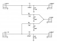
The design is 3rd order and based of Steve Bench's tube crossover design.
My application is woofer and fullrange but other than being a mono system it is in general the same problem. I too will eventually have to deal with summing as the keyboard output is stereo. In my case however both filters need mono input.
Keep in mind that I am coming from a vacuum tube perspective (and working off of a tube design) so some of the R values may seem a bit high for sand. If I find that there is a problem with noise pickup or something I can scale it down but this is my progress so far.
Proposed Schematic...
Attachments
richie00boy said:Unfortunately the diagram above won't work once you connect it to any typical amp as it will load down the filters totally screwing them up.
AndrewT said:Passive filter give the predicted filter characteristic when loaded with a near infinite impedance and fed from a near zero source impedance.
You may have Rs~100r, but much more likely is Rs>=500r from the DAC.
The summing node is loaded with Zin of the power amp AND the impedance of the other feed in parallel with Zin.
Use opamps, or discrete emitter/source followers to give the correct load and source impedances.
Use an inverting amp to sum the two channels for the 0.1 bass channel.
BTW,
a bit of research may find the corrections necessary for the non ideal loading on your passive filters. Might be a good learning opportunity, but much quicker to make the filters active. Have a look here and in Pass and ESP for some very simple Follower circuits (one transistor).
Thanks,
Both posts seem to indicate that impedance will kill a passive filter like this. My First inclination was that I needed op amps but L-R+Buffer is like 3 op-amps per channel+inverting summing opamp for .1+dual 15v power supply and that is a lot complexity for my simple task and my minimalist dream
") .
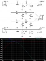
.I noticed an error in my HP calculation as I didn't really have the Zin for the amp compensated. Since I am going to put the amps in the box with the filters what if I just recruit the Zin of the amp in the filter as R2 and what if I adjust Zin of the GC amp to 100K this would give R1 as 10K
By the way, the Super DAC 707 has
LT1364C
Attachments
My First inclination was that I needed op amps but L-R+Buffer is like 3 op-amps per channel+inverting summing opamp for .1+dual 15v power supply and that is a lot complexity for my simple task and my minimalist dream .
A couple of possibilities here. You can run opamps on mono-polar power supply with the addition of a handful of passive components or use a pair of 9V batteries (rechargeable if you like). You can get four opamps in a single DIP which will cover all you need. Pretty simple to wire up really. No PCB needed just put a DIP socket on a small perfboard and wire it all up point to point.
You could also do it with FETs instead of op amps which might sound better but I think that would be a little more complicated to wire up.
As Anon above mentioned ESP has a stereo board that will do this for US$24 and Marchand has mono boards for US$10 with US$0.37 opamps.
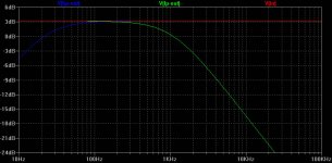
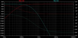
I could add LM317/LM339 to my existing power supply and do the trick but I just don't see what is wrong with what I posted before except that the slope for the high pass may not be steep enough.
I attached the latest plot.
I could add LM317/LM339 to my existing power supply and do the trick but I just don't see what is wrong with what I posted before except that the slope for the high pass may not be steep enough.
I attached the latest plot.
Attachments
mashaffer said:Interesting that this should come up now. I am in the process of wrestling with much the same thing. I was working on an integrated tube amp with triamping crossover built in and decided that I really need a crossover for my keyboard. In order to save my precious tubes and HV power trannies for places where it counts I decided to use cruddy old OpAmps for the MI application.
The design is 3rd order and based of Steve Bench's tube crossover design.
My application is woofer and fullrange but other than being a mono system it is in general the same problem. I too will eventually have to deal with summing as the keyboard output is stereo.
Sorry, mike, I missed this post before. I have been building tube guitar amps for the last several months so I understand about the expensive glass and iron.
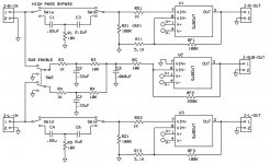
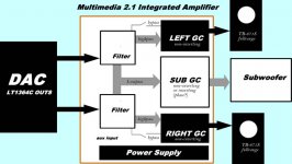
see attached plan for my project. I haven't picked a subwoofer yet or box or anything. The black stuff on the diagram I have already or close anyway.
Attachments
Sorry, mike, I missed this post before. I have been building tube guitar amps for the last several months so I understand about the expensive glass and iron.
Interesting. My first and only tube project was a guitar amp. Do you make these things for fun or profit or both? It was an interesting project for me because I was not only learning about tube amps but also about guitars and their amplification needs. I had so many questions along the way that I broke the record for post per amp on 18watt.com.
The fun part was when the 18 month project suddenly became a 5 month project.
Oh I just made the Firefly and the AX84 October Club over two about two months. I almost made the 18watt.com lite but decided on the AX84 because it wasn't just a copy. It was a lot of work, too much really, and actually the cabinet is not done yet.
here are some photos of my amp.
here are some photos of my amp.
gregorx said:Both posts seem to indicate that impedance will kill a passive filter like this.
It won't kill it, you just have to very aware that the input & output impedance are part of the circuit. I am getting really good results with a 2nd order PLLXO on the Tysen prototypes -- so good that i'm going to try replacing the active woofer in the Fonken/FonkenWoofTL combo.
dave
- Status
- This old topic is closed. If you want to reopen this topic, contact a moderator using the "Report Post" button.
- Home
- Loudspeakers
- Subwoofers
- Simple Line level buffer/active crossover?