planet10 said:
It won't kill it, you just have to very aware
that the input & output impedance are part of the circuit.
dave
One usual topology for filters, passive or active, is:
Buffer - FILTER - Buffer
For filter applications JFET Op-Amps are popular.
Like OPA2134 ( and in past TL071, TL072 ).
JFET op-amps have very high input impedance, take no current from filter circuit,
so they almost does not effect nothing.
As Dave says,
when excluding input/output buffering
we must consider the effects of devices before & after the filter.
They are a part of the filter quality/parameters.
If conditions outside the filter change, the filter parameters will also change.
If conditions in surroundings are pretty static,
the filter performance can be okay and constant.
Lineup
planet10 said:
you just have to very aware
What can we do to this circuit to make is work?
http://www.diyaudio.com/forums/attachment.php?s=&postid=1566121&stamp=1216591552
would simply a 100K POT to ground between C2 and RG and wiper to RG in the LPF section solve the problem. I have recruited the resistors in the HPF section but Andrew had said that the LPF section would not work.
Those filters are very basic and should be possible to get work perfect.
One unknown factor we might need: The output stage parameters for the DAC.
In such a filter circuit, a Spice Simulation + doing AC Analysis, would solve it. Easily")
AC Analysis will show you the resulting filter curve at outputs.
Along with Phase Angle curve.
-----------------------------
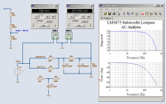
I post one AC Analysis test from my simulator.
I use test frequency 20 Hz at 0.500 Volt RMS input.
The -3 dB is at 300 Hz.
As you notice, I have suggested a change to your filter a bit.
I use two 2 kohm summing input resistors (will equal one 1 kohm).
In this test I run both RIGHT & LEFT inputs from same voltage source
Enjoy
Lineup
One unknown factor we might need: The output stage parameters for the DAC.
In such a filter circuit, a Spice Simulation + doing AC Analysis, would solve it. Easily
AC Analysis will show you the resulting filter curve at outputs.
Along with Phase Angle curve.
-----------------------------
I post one AC Analysis test from my simulator.
I use test frequency 20 Hz at 0.500 Volt RMS input.
The -3 dB is at 300 Hz.
As you notice, I have suggested a change to your filter a bit.
I use two 2 kohm summing input resistors (will equal one 1 kohm).
In this test I run both RIGHT & LEFT inputs from same voltage source
Enjoy
Lineup
Attachments
gregorx said:
What can we do to this circuit to make is work?
http://www.diyaudio.com/forums/attachment.php?s=&postid=1566121&stamp=1216591552
would simply a 100K POT to ground between C2 and RG and wiper to RG in the LPF section solve the problem. I have recruited the resistors in the HPF section but Andrew had said that the LPF section would not work.
You need to make sure that the output impedance of whatever is driving it is low enuff...
LPF section probably won't work because the OpAmp doesn't have a ground reference on the input -- nothing to do with the filter. I would tend yo put an active summer at the input.
Also keep in mind that a chip amp is an opAmp and can be used to create an active 2nd order filter on its own.
dave
For filter applications JFET Op-Amps are popular.
In the process of investigating crossovers for my 6EM7 project I have simulated CF, MOSFET SF, and Op Amp based filters and in the brief look that I had it appeared that the single FET SF performed just as well as the op amp for all practical purposes. I wonder if there might be something to be said for the single stage approach.
planet10 said:I would tend yo put an active summer at the input.
dave
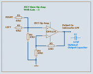
planet10,
something like this, I suppose you mean?
Using one JFET input Op-Amp we can use fairly high impedance resistor inputs.
(it is possible to use higher resistor values, than I have)
The small gain is used to compensate for level loss in input resistor network.
Probably you would need to put a cap at output.
To avoid eventual DC Offset problems in LM3875 power amplifier.
Lineup
Attachments
mashaffer said:... it appeared that the single FET SF
performed just as well as the op amp for all practical purposes.
I wonder if there might be something to be said for the single stage approach.
SF = Source Follower (same as emitter follower for bjt)
Yes, mashaffer.
A single JFET follower would do just as well in most normal filter applications.
This comes from the fact tha most filters are quite easy loads.
There are low AC voltages and AC currents involved
We can mostly use higher resistor values in a filter.
JFET-s have very high input impedance and works very well at lower AC Currents loads.
Such a follower will also work 100% sure in full Class A.
One thing to consider, though, is the power supply for such a stage.
Of course it should be clean.
Fead by a constant current source, this would improve PSRR
more than enough for real hi-fi.
Lineup regards
Thanks Dave, lineup, and Mike
Now this is very interesting. it keeps the minimalist circuit and still gets the active filter.
it seems we could keep the PLLXO on the High Pass.
I don't know of a good simulation model for the LM3875 but I can try to design something. I made the following drawing before I read your posts but I wonder why this wouldn't work.
I can take the DAC appart and figure out what the output impedance is. It has LT1364s as the output buffers.
Also keep in mind that a chip amp is an opAmp and can be used to create an active 2nd order filter on its own
Now this is very interesting. it keeps the minimalist circuit and still gets the active filter.
it seems we could keep the PLLXO on the High Pass.
I don't know of a good simulation model for the LM3875 but I can try to design something. I made the following drawing before I read your posts but I wonder why this wouldn't work.
I can take the DAC appart and figure out what the output impedance is. It has LT1364s as the output buffers.
gregorx said:I can take the DAC appart and figure out what the output impedance is. It has LT1364s as the output buffers.
It should be low enuff not to be a worry....
http://www.linear.com/pc/productDetail.jsp?navId=H0,C1,C1154,C1009,C1022,P1106
You have seen this?
http://www.t-linespeakers.org/tech/filters/passiveHLxo.html
dave
planet10 said:
You have seen this?
Yes. I checked my work against it last night.
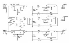
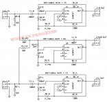
I have tried a design based on your suggestion of using the LM3875 or whatever chip amp as an Active Filter with Gain.
I used the Active Filter Synthesis Tool at Analog.com to get the -12db butterworth filters with gain.
It cuts the part count way down and gets the job done without a new power supply and without low power op amps in the signal chain.
there might be a tolerance concern.
what do you all think of the Active Power Filter solution?
Attachments
I think I finally understand what everybody was trying to say all along. Without a buffer, if your DAC has a series resistor on the output then this will be added to any PLLXO or active XO's series resistor. It will also make a voltage divider with any parallel resistor in an XO. Similarly any resistor to ground resistor in the DAC output would be in parallel with any resistor to ground on the input of the XO. This will mess up the crossover frequency and Q and some cases by a great deal. The output is similar. An impedance will react similarly. So even if I recruited my amps impedance on the output of the XO the input might suffer.
Unless we control the entire signal chain from the last stage to the amp we can't make a universally compatible xo either passive or active without buffers.
I think rather than making a 2.1 system I will make the .1 with the buffers and filters and connect this to a stereo amplifier. That way I can make the minimalist amplifier (2) and put all the buffers etc in the subwoofer (.1) part.
I will report back when I get the .1 done.
Thanks for everyone's patience and help.
I think rather than making a 2.1 system I will make the .1 with the buffers and filters and connect this to a stereo amplifier. That way I can make the minimalist amplifier (2) and put all the buffers etc in the subwoofer (.1) part.
This is essentially what I am planning on doing in my project although mine is a triamping project.
The active crossovers are in the woofer and subwoofer circuits while the main channels use mostly the natural rolloff of the full range drivers with just a switchable input capacitor for an optional 1st order HP at 200Hz to take a bit of load off of both the driver and the spud amp that will be driving the fullrange.
lineup said:planet10,
something like this, I suppose you mean?
Lineup
I just repeat my question to planet10 = dave
You probably missed I was adressing you in one of my posts.
(My post is a response/reply to planet10's note
about buffering left+right before put it into subwoofer LPF filter)
Lineup
regards-------------------
PS. mashaffer, you missed my comment to your JFET Source Follower question/idea.
I would be glad to know if you read my reply/comment.
Also, mashaffer,
you may be kind to leave some response to this post.
I made a basic JFET test schematic for you and did some basic explaining about JFETs.
In this topic which you probably already Have Abandon:
Safe use of unknown small signal transistors
http://www.diyaudio.com/forums/showthread.php?threadid=126791
DS.
no, just invert the bass speaker connections.
Alternatively, use a CFB filter which is inverting and has separate Q(damping), F(frequency), A(gain) controls. This too allows addition of multiple inputs. This can then feed a non-inverting amp agian with inverted bass speaker conns.
Your research has turned into questions. What happened to independent learning?
- Status
- This old topic is closed. If you want to reopen this topic, contact a moderator using the "Report Post" button.
- Home
- Loudspeakers
- Subwoofers
- Simple Line level buffer/active crossover?