So now you are making me wonder if an FRD file import could be a new option for the generation of the correct Semi-Inductance model within Hornresp.
Let me change this a bit.
David could you possibly incorporate a FRD resistance/phase file import option to do the semi-inductance measurements in Hornresp? Many of us have the ability to measure a driver and export an FRD file. And from this I think you could extrapolate the necessary data to create the extended data set.
Last edited:
David could you possibly incorporate a FRD resistance/phase file import option to do the semi-inductance measurements in Hornresp? .
To derive the parameters, ZMA (impedance) files will be needed. At least two would be required, to derive equivalent air compliance (Vas).
To derive the parameters, ZMA (impedance) files will be needed. At least two would be required, to derive equivalent air compliance (Vas).
Yes and impedance and a phase file so correct Brian two files would need to be imported. But many times they are a combined file depending on the test method used.
Yes and impedance and a phase file so correct Brian two files would need to be imported. But many times they are a combined file depending on the test method used.
Hmm... there might be another option - enter the known basic t/s parameters and curve-fit the free-air impedance curve to derive the others...
is there a way for hornresp to get a pretty good sim of the simple two chamber Dynaco A35 enclosure? I shut off the external vents but don't know what to do with the inner vent, which in the real cabinet, had a piece of cloth glued over the 0.375" x 4.875" slit that connected the two chambers.
https://i.imgur.com/s5GbYTq.jpg
https://i.imgur.com/s5GbYTq.jpg
Hi freddi,
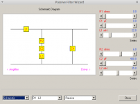
1. Import the attached record and edit the driver and enclosure parameter values as necessary.
2. Use the Loudspeaker Wizard to adjust the absorbent filling material in segment 1.
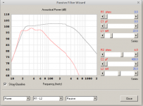
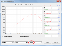
3. The system response is given by Output 2.
Kind regards,
David
1. Import the attached record and edit the driver and enclosure parameter values as necessary.
2. Use the Loudspeaker Wizard to adjust the absorbent filling material in segment 1.
3. The system response is given by Output 2.
Kind regards,
David
Attachments
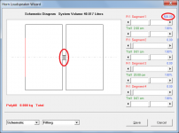
edit the driver and enclosure parameter values as necessary.
For example - change the value of S2 from 5.00 sq cm to 11.79 sq cm if the interconnecting slit is 0.375" x 4.875".
many thanks David - its interesting to see that a notch in displacement can occur below 20Hz - would that hold up under various reasonable drive levels with such a small interconnecting vent? - being internal no one should hear it wheeze (unless through the cone. BEST ! Freddy
Would it be possible to implement your suggested optional approach using an Excel spreadsheet, perhaps?
Now don't you go trying to plant that seed in my head, LOL. I've got enough work as it is maintaining the design workbooks...
")
Technically, doing it in Excel should be possible. And Excel does provide the goal-seeking algorithm built in.
Now don't you go trying to plant that seed in my head, LOL. I've got enough work as it is maintaining the design workbooks...
Technically, doing it in Excel should be possible. And Excel does provide the goal-seeking algorithm built in.
There is a forum member here who has done this already. We have been discussing it quietly in the background. So no pressure on you Master Steele. Your spreadsheets are pretty cool.
Still waiting for a front loaded horn folder!
Your only evil when you are awake!
Niiiiiice! ( In most sinister Mr. Burns Voice of course )
Hi Brian,
Would it be possible to implement your suggested optional approach using an Excel spreadsheet, perhaps?
Kind regards,
David
Niiiiiice! ( In most sinister Mr. Burns Voice of course )
Still waiting for a front loaded horn folder!
You didn't see my "W-bin" workbook? It's still a work in progress...
many thanks David - its interesting to see that a notch in displacement can occur below 20Hz - would that hold up under various reasonable drive levels with such a small interconnecting vent? - being internal no one should hear it wheeze (unless through the cone. BEST ! Freddy
Hi Freddy,
The model I suggested is the closest that you can get using Hornresp, but it is by no means perfect
. Hopefully the power response prediction should be reasonable though, provided that the Output 2 result is used.It appears that the notch you are seeing is due to the effect of the very small hole in the second chamber. Notice how if you increase S5 to 1.00 sq cm for example, the notch disappears. I have no experience with dual chamber designs, but presumably the notch would not be present in a practical system, if the second chamber was completely sealed.
For a serious analysis it would be safer to use AkAbak, but I gained the impression that you were looking for an indicative result only, which is why I was prepared to provide the suggested Hornresp "compromise" model
.Kind regards,
David
And Excel does provide the goal-seeking algorithm built in.
That's why I suggested using it
.Is possible to calculate whith Hornresp Helmholtz resonator like Technics SB-7000?
Hi Orion33,
Yes, bass-reflex systems can be simulated in Hornresp. The easiest way to get started is to create a representative design using the Input Wizard, and then change the input parameter values to suit. Select:
Help > Input Wizard > Half Space > Direct Radiator > Ported Box ......
Kind regards,
David
Thank you for answer, David.Yes, bass-reflex systems can be simulated in Hornresp. The easiest way to get started is to create a representative design using the Input Wizard, and then change the input parameter values to suit.
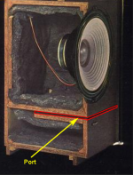
But Helmholtz resonator is not bass-reflex system. See please picture
.JPG)
Resonanse camera is not connected to main box whereas bass reflex port is directly connected. I tryed create think section with maximal acoustical lining resistance but its behavior is diffrent from closed box. Or am I wrong?
- Home
- Loudspeakers
- Subwoofers
- Hornresp