Thanks for the links, the latter I have viewed. From looking at the various horn configurations, I thought the design was most closely represented by the offset horn. But as your first link defines trapped horn as those that have the driver part way along a horn segment I guess this also applies to the design.
Hi CUTTING EDGE CNC,
A possible alternative model could be as shown in the attachments.
Kind regards,
David
EDIT - Use the Loudspeaker Wizard to add the necessary absorbent filling material to the transmission line.
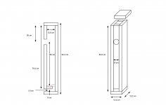
Thanks very much David. I have attached an edited drawing showing the dimensions of a section 3.8cmx10cm and 1.2cm long. Could you please let me know if this should be represented as a horn segment or not. and if so, if there are more than 4 segments, how is the data entered?
On a side note, after reading the recent comments on this thread it must be irritating and disheartening for you to have to put up with pedants. It's one thing for a user to point out a potential glitch to aid the development of the software, but to criticise in such a pius fashion is offensive.
Attachments
 .....
.....
I have attached an edited drawing showing the dimensions of a section 3.8cmx10cm and 1.2cm long. Could you please let me know if this should be represented as a horn segment or not. and if so, if there are more than 4 segments, how is the data entered?
Hi CUTTING EDGE CNC,
Ideally the 3.8cm x 10cm x 1.2cm duct volume should be modelled as a separate segment, however because Hornresp is limited to four segments it is necessary to make a simplifying assumption, as bjorno has done.
In my example I simply used your 10.2cm figure for the final segment length without checking the dimensions on the drawing. Somewhere around 14 cm would appear to be a more accurate figure to use, as shown by bjorno.
Kind regards,
David
But as your first link defines trapped horn as those that have the driver part way along a horn segment I guess this also applies to the design.
Just to clarify, the design in question is a mass-loaded transmission line loudspeaker, and should be modelled in Hornresp as an offset driver (OD) system, not a tapped horn (TH or TH1) system.
Polarity ?
@ David McBean CodeMaster")
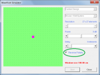
Hi, even with the latest version i've searched right through the HLP file, & cannot find how to reverse the polarity of a driver ! Apart from where it mentions it in the Wavefront Simulator, but i want to be able to do it generally.
Am i going blind, or ?
@ David McBean CodeMaster
Hi, even with the latest version i've searched right through the HLP file, & cannot find how to reverse the polarity of a driver ! Apart from where it mentions it in the Wavefront Simulator, but i want to be able to do it generally.
Am i going blind, or ?
Hi, even with the latest version i've searched right through the HLP file, & cannot find how to reverse the polarity of a driver ! Apart from where it mentions it in the Wavefront Simulator, but i want to be able to do it generally.
Hi Zero D,
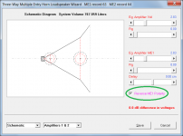
The polarity of a source / driver can be reversed in the Wavefront Simulator tool and in the Multiple Entry Horn Wizard, but not generally.
If you are seeking to reverse the polarity of selected drivers in either a multiple driver or a multiple speaker array, then for the results to be meaningful it would be necessary for the Hornresp simulation model to take into account the relative geometric positions of each of the multiple drivers or speakers in the array. This would require additional input data values, and would complicate things enormously.
Another one for AkAbak, it seems.
Kind regards,
David
Attachments

@ David McBean
OH, that's a pity ! Well can we reverse the polarity of Just one source/driver then, if not multiples, & if so how ?
What surprises me is, if it can be done for a Multiple Entry Horn, then that surely means it is Actually possible to do !
If you figure out how to include a reverse polarity option/s, this would be VERY useful to not only me, i'm Convinced of it. Please have a good think about it, @ your convenience of course
Hi Mark,
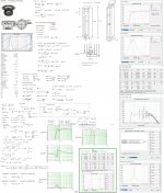
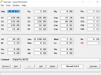
I get a slightly longer length for L45.
To two decimal places, the drawing centre line lengths taken from the given drawing dimensions are:
L12 = 23.20 + 7.85 + 6.20 = 37.25 cm
L23 = 29.40 + 7.85 + 8.80 = 46.05 cm
L34 = 0.01 cm
L45 = 1.80 + 3.40 + 1.80 = 7.00 cm
As bjorno has shown in Post #6963, acoustical filling material / filtering will be required to achieve an acceptable performance.
Kind regards,
David
From your drawing I get a total center line length of 83.3cm. And a port length again by center line of 6.4 cm
I get a slightly longer length for L45.
To two decimal places, the drawing centre line lengths taken from the given drawing dimensions are:
L12 = 23.20 + 7.85 + 6.20 = 37.25 cm
L23 = 29.40 + 7.85 + 8.80 = 46.05 cm
L34 = 0.01 cm
L45 = 1.80 + 3.40 + 1.80 = 7.00 cm
Have you looked at the response of the simulation?
As bjorno has shown in Post #6963, acoustical filling material / filtering will be required to achieve an acceptable performance.
Kind regards,
David
Well can we reverse the polarity of Just one source/driver then
Hi Zero D,
I'm intrigued
.Why would you want to simulate a single driver loudspeaker system with the driver polarity reversed - what differences are you expecting to see?
Can you provide a specific example of what you have in mind, please?
Kind regards,
David
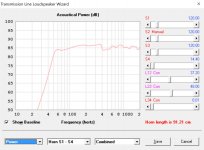
From your drawing I get a total center line length of 83.3cm. And a port length again by center line of 6.4 cm
Your simulation as setup is a length of 85.2 cm and a port length of 6 cm.
Have you looked at the response of the simulation?
View attachment 591611
Thanks for looking at this, I thought the the transmission line wizard response with the filler dampening was the relevant graph in this situation.
I'll take another look at the dims of my diagram.
Attachments
Hi Mark,
I get a slightly longer length for L45.
To two decimal places, the drawing centre line lengths taken from the given drawing dimensions are:
L12 = 23.20 + 7.85 + 6.20 = 37.25 cm
L23 = 29.40 + 7.85 + 8.80 = 46.05 cm
L34 = 0.01 cm
L45 = 1.80 + 3.40 + 1.80 = 7.00 cm
As bjorno has shown in Post #6963, acoustical filling material / filtering will be required to achieve an acceptable performance.
Kind regards,
David
David, thanks for pointing out these late night/hasty mistakes. I should really do this in the day!
Can I just check that the graphs generated by pressing calculate in the data input window do not take account of any of the filling used in the t/l wizard? If this is the case are the wizard graphs a more realistic response for a MLTL?
I am not so. If Hornresp had no potential, i would not try to get it repaired.I really hate it when anybody is disrespectful of a person who has earned the respect of so many.
Why are you, not only David but many other persons, too, lying about power? You pass pressure off as power, and you pass power off as energy.
Do not harm persons, who want to calculate power. I have not yet experienced you harming anyone, but the way you behave it will not take long before you do.
Yes you are. It´s the choice of words you use and the ongoing ignoring of what others say. Even if you were right with your argument, you are not in the position to make demands. And the way you talk about the topic is very demanding.I am not so.
It´s one thing to make a suggestion or to point something out - but if David decides to leave it like that (regardless of your oppinion on the matter) - it should be respected. And that´s where you are disrespectful.
Hi Mark,
I get a slightly longer length for L45.
To two decimal places, the drawing centre line lengths taken from the given drawing dimensions are:
L12 = 23.20 + 7.85 + 6.20 = 37.25 cm
L23 = 29.40 + 7.85 + 8.80 = 46.05 cm
L34 = 0.01 cm
L45 = 1.80 + 3.40 + 1.80 = 7.00 cm
Serves me right. I looked at the port numbers I wrote down and sure enough made a mistake. Thanks for looking at it.
The stuffing issue is a given as it is a transmission line. The response question was rhetorical. I'm dumb, but not that dumb.
This website is about communicational machines. He uses Hornresp to process the world, i use this post to process the world. We all --David, me, you, every one of 7.5B-- are propagandists, propaganda is our arena and our retreat, our day and our nite. I propagate a physical truth, he propagates twisting it.Yes you are. It´s the choice of words you use and the ongoing ignoring of what others say. Even if you were right with your argument, you are not in the position to make demands. And the way you talk about the topic is very demanding.
It´s one thing to make a suggestion or to point something out - but if David decides to leave it like that (regardless of your oppinion on the matter) - it should be respected. And that´s where you are disrespectful.
- Home
- Loudspeakers
- Subwoofers
- Hornresp