Hi simonpink,
For a standard folded construction, with equal duct height (width) throughout the enclosure, you might set the height to the internal enclosure height (width), e.g.: 40cm, and use smaller increments, e.g.: 2.54 (if you want to work in inches). I like to just calculate the values for duct height @ e.g.: S1 in a spreadsheet, and draw the results in a CAD program as a profile. Then I get my values from that drawing.
Regards,
Last edited:
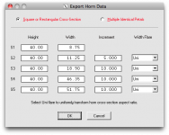
So I put 40 in the height column like this?
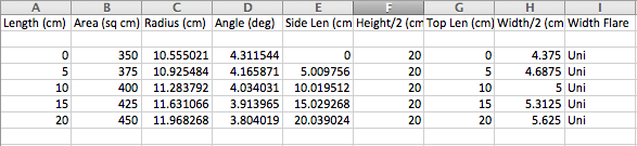
When I open the exported excel file from that I've got height measurements of 20cm? And the product of the width and height isn't equal to the area at each increment along the S1 section, or any of them?
When I open the exported excel file from that I've got height measurements of 20cm? And the product of the width and height isn't equal to the area at each increment along the S1 section, or any of them?
Attachments
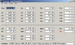
@simonpink you need to set height to for example 33 cm for a 12 inch woofer, then export.
for a 5 segment tapped horn you need Th1 I think but then you have bad respons as I see. I did use TH1
I do see you use a dayton UM-15, this woofer is not a good candidate, high qts, high vas, low FS beauty
for closed box. Transition from S1 to S2 it is difficult to mount a speaker.
regards
for a 5 segment tapped horn you need Th1 I think but then you have bad respons as I see. I did use TH1
I do see you use a dayton UM-15, this woofer is not a good candidate, high qts, high vas, low FS beauty
for closed box. Transition from S1 to S2 it is difficult to mount a speaker.
regards
Attachments
Last edited:
Hi David
Still I get strange outcomes from hornresp when export conical.
Because of this I don,t trust this because if wrong I possibledo hours
or work for nothing when folding, when I do export exponential then it works
also par and uni works.
everything is in zip also design import.
regards
kees
Still I get strange outcomes from hornresp when export conical.
Because of this I don,t trust this because if wrong I possibledo hours
or work for nothing when folding, when I do export exponential then it works
also par and uni works.
everything is in zip also design import.
regards
kees
Attachments
Last edited:
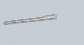
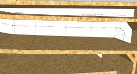
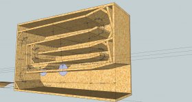
I have here a sample of the box, look at the flare and tekst.
it is exp, the con one has a lot of other values some 1 cm more flare somewhere around 150 cm from S2 speaker startpoint, therefore I did not trust the conical one, exp seems to fit wel but has bumps in flare on some places, maybe this is because of sketchup...
regards
kees
it is exp, the con one has a lot of other values some 1 cm more flare somewhere around 150 cm from S2 speaker startpoint, therefore I did not trust the conical one, exp seems to fit wel but has bumps in flare on some places, maybe this is because of sketchup...
regards
kees
Attachments
Hornresp Update 3220-130622
Hi Everyone,
Changes:
1. The problem reported by Kees in Post #3547 has been fixed.
2. A fatal error occurred when trying to print a hard copy of the group delay chart. This problem has now also been fixed - the bug was introduced when the Filter Wizard tool was added.
Kind regards,
David
Hi Everyone,
Changes:
1. The problem reported by Kees in Post #3547 has been fixed.
2. A fatal error occurred when trying to print a hard copy of the group delay chart. This problem has now also been fixed - the bug was introduced when the Filter Wizard tool was added.
Kind regards,
David
Still I get strange outcomes from hornresp when export conical.
Hi Kees,
Thanks for reporting this issue. The problem has been fixed in the latest release.
Width / 2 values now remain constant along the length of the horn when the entered S1 and S2 width values are the same. Previously under some circumstances the Width / 2 values could vary.
Note that Height / 2 values can sometimes vary even when the entered S1 and S2 height values are the same. This is because the Con, Exp and Uni flare settings apply to the width, not the height.
Kind regards,
David
Hi David
Indeed the width do give proper outcome, the height is still errorrous, give on some places even a 0,5 cm error.
I find on the internet of hornresp learning that we have to use width, it is strange but is not a problem further for the build itself..
thanks
kees
Indeed the width do give proper outcome, the height is still errorrous, give on some places even a 0,5 cm error.
I find on the internet of hornresp learning that we have to use width, it is strange but is not a problem further for the build itself..
thanks
kees
Attachments
Filter Wizard Question
Hi David,
I noticed, that switching back and forth between the Butterworth and the Linkwitz-Riley 4th order filters, the difference in SPL that the Filter Wizard plots does not agree with simulations in other programs, e.g.: Bagby's Woofer Designer (there is very little response difference between the two in Bagby's). The Filter Wizard does seem to be consistent, e.g.: both SPL and displacement are more attenuated in L/R than Bw.
I would expect the SPL response to be quite close in the passband, even if the attenuation is different at the choosen crossover points (-3dB for Bw and -6dB for L/R); or are the crossover point just too close together?
Regards,
Attachments
Hi Kees,
As mentioned in my previous post, making the S1 and S2 height values the same does not necessarily mean that the Height / 2 values will be constant over the length of the horn. This is not an error in the program. It occurs because the width flare setting determines the overall outcome, not the fact that S1 height = S2 height. The width at a given distance along the segment is calculated using the chosen width flare setting (Con, Exp, or Uni). The height value at that point is then determined by dividing the known cross-sectional area by the width.
If you require the actual constructed horn to have two parallel sides, and the other two sides to be flat panels, then a parabolic horn segment should be specified, and the S1 width and S2 width values should be the same. Currently it doesn’t matter if the selected width flare is Con, Exp or Uni, but on reflection, I think I will change the code so that the Uni width flare works in all situations as it should - uniformly transforming the horn cross-section aspect ratio, even when S1 width = S2 width. This means that you would then need to use either Con or Exp width flare to specify parallel sides - the sides would no longer be parallel if Uni width flare is selected because of the way that the cross-section aspect ratio transforms along the length of the horn.
Thanks again for your ongoing feedback. Over time, it has enabled us to find and fix three quite subtle bugs in this part of the program.
Kind regards,
David
Indeed the width do give proper outcome, the height is still errorrous, give on some places even a 0,5 cm error.
As mentioned in my previous post, making the S1 and S2 height values the same does not necessarily mean that the Height / 2 values will be constant over the length of the horn. This is not an error in the program. It occurs because the width flare setting determines the overall outcome, not the fact that S1 height = S2 height. The width at a given distance along the segment is calculated using the chosen width flare setting (Con, Exp, or Uni). The height value at that point is then determined by dividing the known cross-sectional area by the width.
I find on the internet of hornresp learning that we have to use width, it is strange but is not a problem further for the build itself..
If you require the actual constructed horn to have two parallel sides, and the other two sides to be flat panels, then a parabolic horn segment should be specified, and the S1 width and S2 width values should be the same. Currently it doesn’t matter if the selected width flare is Con, Exp or Uni, but on reflection, I think I will change the code so that the Uni width flare works in all situations as it should - uniformly transforming the horn cross-section aspect ratio, even when S1 width = S2 width. This means that you would then need to use either Con or Exp width flare to specify parallel sides - the sides would no longer be parallel if Uni width flare is selected because of the way that the cross-section aspect ratio transforms along the length of the horn.
Thanks again for your ongoing feedback. Over time, it has enabled us to find and fix three quite subtle bugs in this part of the program.
Kind regards,
David
I noticed, that switching back and forth between the Butterworth and the Linkwitz-Riley 4th order filters, the difference in SPL that the Filter Wizard plots does not agree with simulations in other programs, e.g.: Bagby's Woofer Designer (there is very little response difference between the two in Bagby's). The Filter Wizard does seem to be consistent, e.g.: both SPL and displacement are more attenuated in L/R than Bw.
I would expect the SPL response to be quite close in the passband, even if the attenuation is different at the choosen crossover points (-3dB for Bw and -6dB for L/R); or are the crossover point just too close together?
Hi Oliver,
I am not sure what the other programs are doing, but as far as I can see the Hornresp results should be okay.
It is important to remember that in the Hornresp case we are applying a band-pass filter to a single signal, not combining two signals using a crossover network.
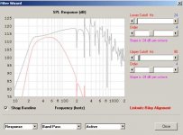
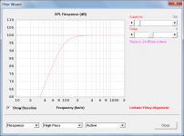
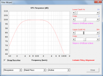
Attachment 1 shows the response for a 4th-order Linkwitz-Riley high-pass filter with a cutoff frequency fc of 100 Hz. As expected, the response is -6dB at fc. Notice how the response actually starts to fall off at around 400 Hz (2 octaves above fc).
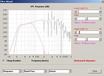
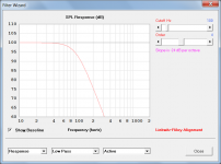
Attachment 2 shows the response for a 4th-order Linkwitz-Riley low-pass filter with a cutoff frequency fc of 100 Hz. As expected, the response is -6dB at fc. Notice how the response actually starts to fall off at around 25 Hz (2 octaves below fc).
For your given example, the high-pass fc is 24 Hz and the low-pass fc is 80 Hz.
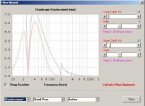
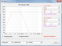
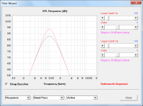
For a 4th-order Linkwitz-Riley alignment, the low-pass fc would need to be about 384 Hz not to cause any attenuation of the band-pass signal. For fc = 24 Hz the high-pass filter starts to fall off around 24 x 4 = 96 Hz. For fc = 384 Hz the low-pass filter also starts to fall off around 384 /4 = 96 Hz. Attachment 3 refers.
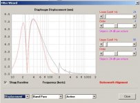
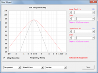
For a 4th-order Butterworth alignment, the low-pass fc would need to be about 96 Hz not to cause any attenuation of the band-pass signal. For fc = 24 Hz the high-pass filter starts to fall off around 24 x 2 = 48 Hz. For fc = 96 Hz the low-pass filter also starts to fall off around 96 / 2 = 48 Hz. Attachment 4 refers.
As mentioned in earlier posts, I am a little out of my comfort zone when it comes to the practical application of filters, so if you see anything wrong in what I have said above, please do not hesitate to let me know
") .
.Kind regards,
David
Attachments
Hi Kees,
As mentioned in my previous post, making the S1 and S2 height values the same does not necessarily mean that the Height / 2 values will be constant over the length of the horn. This is not an error in the program. It occurs because the width flare setting determines the overall outcome, not the fact that S1 height = S2 height. The width at a given distance along the segment is calculated using the chosen width flare setting (Con, Exp, or Uni). The height value at that point is then determined by dividing the known cross-sectional area by the width.
If you require the actual constructed horn to have two parallel sides, and the other two sides to be flat panels, then a parabolic horn segment should be specified, and the S1 width and S2 width values should be the same. Currently it doesn’t matter if the selected width flare is Con, Exp or Uni, but on reflection, I think I will change the code so that the Uni width flare works in all situations as it should - uniformly transforming the horn cross-section aspect ratio, even when S1 width = S2 width. This means that you would then need to use either Con or Exp width flare to specify parallel sides - the sides would no longer be parallel if Uni width flare is selected because of the way that the cross-section aspect ratio transforms along the length of the horn.
Thanks again for your ongoing feedback. Over time, it has enabled us to find and fix three quite subtle bugs in this part of the program.
Kind regards,
David
Your welkome.
I have did this as a exp flare one, using panel parts and parallel sides tapped horn, it give a better delay and smaller box 211 liters, make it conical what I think it is more that way do not give many change just little, length is fine within 0,7 cm and flares are max 0,1 mm difference, most are precise.
regards
kees
Attachments
Posts #3552 and #3554
Hi David,
Thank you for you lengthy explanantion in Post #3554. I agree with everything you are saying there. But, I'm still not quite sure about the difference in passband response between the two filter types, it may well be that the turnover points are just too close together. Now I'll have more studying to do as to what I'm missing when looking @ Babgy's graphs.
Regards,
(By the way, this is my second attempt to post a reply, seems the last one was lost in the cloud?)
Hornresp Update 3220-130625
Hi Everyone,
As foreshadowed in Post #3553, the horn data export 'Uni' option now uniformly transforms the horn rectangular cross-section aspect ratio even when S1 width = S2 width. In the previous release the width dimension was held constant along the length of the horn when S1 width = S2 width.
Kind regards,
David
Last edited:
But, I'm still not quite sure about the difference in passband response between the two filter types, it may well be that the turnover points are just too close together. Now I'll have more studying to do as to what I'm missing when looking @ Babgy's graphs.
Hi Oliver,
For the high-pass and low-pass filter responses not to interact, it would appear that the HF and LF cutoff frequencies need to be at least 2 octaves apart for a Butterworth alignment, and 4 octaves apart for a Linkwitz-Riley alignment. This would certainly seem to suggest that the turnover points in your example may perhaps be too close together.
Could you please let me know in due course, if you indeed find out why the Bagby graphs are different.
Out of interest, I couldn't resist doing a few more 'sanity checks'
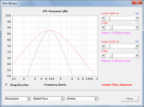
. In each case, the un-filtered SPL response is a constant 100dB across the frequency range, and the high-pass and low-pass cutoff frequencies are both 100 hertz. Reassuringly, all results are as expected.Attachment 1
Red trace - 4th-order Butterworth, 2 x -3dB = -6dB at fc (94dB - 100dB)
Grey trace - 4th-order Linkwitz-Riley, 2 x -6dB = -12dB at fc (88dB - 100dB)
Attachment 2
Red trace - 2nd-order Butterworth, 2 x -3dB = -6dB at fc (94dB - 100dB)
Grey trace - 4th-order Butterworth, 2 x -3dB = -6dB at fc (94dB - 100dB)
Attachment 3
Red trace - 2nd-order Linkwitz-Riley, 2 x -6dB = -12dB at fc (88dB - 100dB)
Grey trace - 4th-order Linkwitz-Riley, 2 x -6dB = -12dB at fc (88dB - 100dB)
Kind regards,
David
Attachments
David,
I don't understand what you mean with
A 2nd order Butterworth has Q=1/sqrt(2)= ~0.707 and the turn over frequency F-3dB is at the 90degree phase change.
A 4pole cascaded Butterworth still has a Q=~0.707 and F-3dB at the same frequency. This is achieved using a staggered pair of 2pole filters, neither of which is Butterworth.
If one cascades two 2pole Butterworths, one ends up with a Q=0.5 and F-6dB at the turn over frequency. This will be a 4pole Linkwitz Riley.
I don't understand what you mean with
and similarly for the others.Red trace - 4th-order Butterworth, 2 x -3dB = -6dB at fc (94dB - 100dB)
Grey trace - 4th-order Linkwitz-Riley, 2 x -6dB = -12dB at fc (88dB - 100dB)
A 2nd order Butterworth has Q=1/sqrt(2)= ~0.707 and the turn over frequency F-3dB is at the 90degree phase change.
A 4pole cascaded Butterworth still has a Q=~0.707 and F-3dB at the same frequency. This is achieved using a staggered pair of 2pole filters, neither of which is Butterworth.
If one cascades two 2pole Butterworths, one ends up with a Q=0.5 and F-6dB at the turn over frequency. This will be a 4pole Linkwitz Riley.
- Home
- Loudspeakers
- Subwoofers
- Hornresp