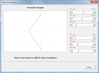
One question, is it possible to expand the tool with magnet dimensions so it can compensate for the volume, taken by the driver, at S4?
Hi Djim,
I looked into this when I first started working on the tool. Unfortunately it is not really a practical proposition because of the many different ways that the driver chassis and magnet assembly can be constructed. Often the chassis is a complex casting having a significant volume of its own, and the magnet assembly is not just a simple cylindrical shape.
Kind regards,
David
Exactly, there are too many drivers with heat sinks in complex shapes, its hard to judge the Volumen by giving a geometry.. Most manufactureres don´t quote the volume of the driver, in some cases of frontloaded horns with very small backchambers, this can lead to a lot of trying around with prototypes in the woodwork. We used to put the magnet in a plastik sack and dipp it in a full bucket of water, gathering the "lost" water in a pan benath - then measuring the amount of water with a kitchen tool I don´t know the english espression for - some measurement cupI looked into this when I first started working on the tool. Unfortunately it is not really a practical proposition because of the many different ways that the driver chassis and magnet assembly can be constructed. Often the chassis is a complex casting having a significant volume of its own, and the magnet assembly is not just a simple cylindrical shape.
") Together with the geometrie of the cone, this was close enough.
Together with the geometrie of the cone, this was close enough. David, would it be possible to teach hornresp to do that or at least make some coffee?
Just kidding, of course (not the waterbucket part, we really did that)
Some drivers do have invers dust-caps (RCF L12P530 e.g.), would it be possible to extend the driver-front-volume tool to do that (H3>H2) ?
Some Drivers also have different "flare rates", the area doesn´t increase parabolic (hm, is it parabolic, not sure) - slicing the cone in half its not a straight line but curved, I´d have to look up the exact english terms... But I guess it´s close enough now, most of the time one can´t find out the real expansion rate after all.....
Thanks for all the effort you put in this over all these years!!
Last edited:
I was interested in your opinion.
Hi Martin,
When it comes to things like this, your guess is as good as mine
.For a tapped horn, I think I would probably just include a suitably-sized throat chamber to address the 'cone compensation' issue at the throat end, and probably just ignore the fact that the driver intrudes into the acoustic path at the mouth end.
Kind regards,
David
Hi Sabbelbacke,
I will have a look.
I figured that a conical diaphragm would be a reasonable compromise. As you point out, determining the precise profile can be quite difficult. Also, the diaphragm surface itself is sometimes ribbed or corrugated, which further complicates matters.
You're welcome. And thanks to everyone else who has had a kind word to say about the new tool.
Kind regards,
David
Some drivers do have invers dust-caps (RCF L12P530 e.g.), would it be possible to extend the driver-front-volume tool to do that (H3>H2) ?
I will have a look
.Some Drivers also have different "flare rates", the area doesn´t increase parabolic (hm, is it parabolic, not sure) - slicing the cone in half its not a straight line but curved, I´d have to look up the exact english terms... But I guess it´s close enough now, most of the time one can´t find out the real expansion rate after all.....
I figured that a conical diaphragm would be a reasonable compromise. As you point out, determining the precise profile can be quite difficult. Also, the diaphragm surface itself is sometimes ribbed or corrugated, which further complicates matters.
Thanks for all the effort you put in this over all these years!!
You're welcome. And thanks to everyone else who has had a kind word to say about the new tool
.Kind regards,
David
At first I did not understand the dimension designations.
Hi Mark,
D1, D2 and D3 were intended to represent diameter values, with H1, H2 and H3 representing height values.
Perhaps H1, H2 and H3 would be better off as D4, D5 and D6, signifying depth or distance, rather than height.
Kind regards,
David
I'd leave it be as you started it.
Hi Mark,
Thanks for the feedback.
I like your comment - it means that I don't have to do anything
.Kind regards,
David
Could the units of measurement be added to the input screens?
Hi Andrew,
This has been requested previously
. The change has not been implemented because I want the input forms to remain as uncluttered as possible.As far as the main input parameters window is concerned, moving the mouse pointer over an input box shows the units in the status bar panel at the bottom of the window.
Units are included on the Filter Wizard and Driver Front Volume tool sliders simply because this information is not given elsewhere.
Kind regards,
David
The max spl view is a bit confusing, as the drive voltage changes as the impedance changes. You can of course get information you want by F3 sample, but if the graph cursor updated drive voltage, watts, attempted excursion, pascals at throat and throat velocity it might be handy.
I've been using spl graph set and a nominal 1w for years and I just realized that the max spl graph was variable in drive voltage. I know, foolish me, right?
I've been using spl graph set and a nominal 1w for years and I just realized that the max spl graph was variable in drive voltage. I know, foolish me, right?
The max spl view is a bit confusing, as the drive voltage changes as the impedance changes. You can of course get information you want by F3 sample, but if the graph cursor updated drive voltage, watts, attempted excursion, pascals at throat and throat velocity it might be handy.
Hi hellonwheels,
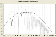
The Hornresp Maximum SPL chart shows the SPL 'performance envelope' when limited by either Pmax driver input power or Xmax diaphragm displacement.
For the black-trace section of the chart, "watts" is constant at the Pmax value.
For the red-trace section of the chart, "attempted excursion" is constant at the Xmax value.
From the Maximum SPL chart:
* Select the Sound Pressure chart to see "pascals at throat".
* Select the Particle Velocity chart to see "throat velocity".
* Select the Diaphragm Displacement chart to see "attempted excursion".
Then from the Diaphragm Displacement chart:
* Select the Pressure chart to see "pascals at diaphragm".
* Select the Velocity chart to see "diaphragm velocity".
I would prefer not to add more data to the Maximum SPL chart cursor sampling output. The chart shows the maximum SPL, which is the sample result given.
Kind regards,
David
Hi! And thank you.
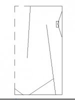
If flare mouth is on the rear of the cabinet like here http://www.diyaudio.com/forums/full-range/144190-bigger-frugel-horn-bugelhorn-12.html#post1859185
How should we measure "path length difference" for combined SPL response? The shortest distance between mouth/cone centres around side panel or a little more due to floor/wall elongation?
Maybe rear mouth in full-range driver (OD setup) is preferable because we can make longer 1st segment (makes nice direct radiation), big front baffle (it makes "bigger" sound IMO), we don't hear higher harmonics from flare. Am I right or front mouth horns are more gainy, sim predictable and room indifferent that they are comme il faut?
Have I to implement S1, S2, S3 area correction (multiply to say 1.1) due to rectangular cross-section (not circular as simulated)? We really appreciate your work. Best wishes.
Attachments
Last edited:
Hi rrr969,
To keep things simple, I would probably just use the following:
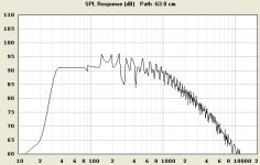
Path length difference = -(cabinet rear width / 2 + cabinet side depth)
For example, if the loudspeaker cabinet is rectangular, and 30 cm wide by 48 cm deep, then the path length difference would be -(30 / 2 + 48) = -63 cm (by definition, the value is negative because the distance from the rear-facing horn mouth to the listener is greater than the distance from the front-facing direct radiator diaphragm to the listener).
If the loudspeaker is positioned close to a wall or in a corner, then a rear-facing horn should theoretically have better acoustical loading at the mouth, and therefore a stronger and a slightly smoother response. It really all depends on your overall system design aims as to whether you use a front-facing or rear-facing horn. Others having practical experience with such systems may wish to comment further.
It is not necessary to adjust the S1, S2, and S3 values. The cross-sectional area is the important parameter, not whether the shape of the actual constructed section is circular or rectangular.
Kind regards,
David
How should we measure "path length difference" for combined SPL response?
To keep things simple, I would probably just use the following:
Path length difference = -(cabinet rear width / 2 + cabinet side depth)
For example, if the loudspeaker cabinet is rectangular, and 30 cm wide by 48 cm deep, then the path length difference would be -(30 / 2 + 48) = -63 cm (by definition, the value is negative because the distance from the rear-facing horn mouth to the listener is greater than the distance from the front-facing direct radiator diaphragm to the listener).
Maybe rear mouth in full-range driver (OD setup) is preferable because we can make longer 1st segment (makes nice direct radiation), big front baffle (it makes "bigger" sound IMO), we don't hear higher harmonics from flare. Am I right or front mouth horns are more gainy, sim predictable and room indifferent that they are comme il faut?
If the loudspeaker is positioned close to a wall or in a corner, then a rear-facing horn should theoretically have better acoustical loading at the mouth, and therefore a stronger and a slightly smoother response. It really all depends on your overall system design aims as to whether you use a front-facing or rear-facing horn. Others having practical experience with such systems may wish to comment further.
Have I to implement S1, S2, S3 area correction (multiply to say 1.1) due to rectangular cross-section (not circular as simulated)?
It is not necessary to adjust the S1, S2, and S3 values. The cross-sectional area is the important parameter, not whether the shape of the actual constructed section is circular or rectangular.
Kind regards,
David
Last edited:
Hornresp Update 3220-130511
Hi Everyone,
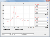
The Filter Wizard tool can now calculate the overall group delay of a passive filter and loudspeaker combination.
My thanks to Jean-Michel for his comment in Post #3406 which prompted me to develop a method to determine group delay values in real time.
Kind regards,
David
Hi Everyone,
The Filter Wizard tool can now calculate the overall group delay of a passive filter and loudspeaker combination.
My thanks to Jean-Michel for his comment in Post #3406 which prompted me to develop a method to determine group delay values in real time.
Kind regards,
David
Attachments
- Home
- Loudspeakers
- Subwoofers
- Hornresp