I can think of a gentleman who was doing exactly what is described. Josh Ricci. He has some good ideas, and shows a great thinking ability.
Agreed, he does have good ideas and great ability (and a seemingly never ending pool of resources) but his sims (Othorn in particular, since it's the only one I've looked at in any detail) don't match his measurements very well at all. I'm not sure why and I haven't independently simmed the Othorn directly from the plans. But his sim vs measurement of Othorn is pretty different.
He also likes using AkaBak thinking that there is a better overall simulation of what goes on.
Davids reply was most salient. But I cannot seem to find it!
So when I'm not looking for it it will pop up.
Short but sweet David was able to sim in four segments what was done with TLC in a great many more segments in AkaBak.
In the low end of sound reproduction it does not matter as much as most people think.
getting accuracy to the nearest mm only matters in the high frequency horns. And even there you would be very surprised what works and what will still work with compromises.
Are you ok with the sim I posted that shows a downward trend of 2 db covering the entire bandwidth between 30 and 70 db? (It's 1 db high at tuning and 1 db low at 60 hz, crossing over the PAR sim at the midpoint.)
Like I said, this is a fairly extreme case and most of the time this won't happen, but on the other hand I consider this to be a pretty significant error as shown and I can produce results even worse than this.
Anyway, David doesn't want more segments and I respect that so there's not much point in discussing this further, at least in this thread.
I'll check out the posts by soho54 and Brian Steele, though I have limited time to read forum threads. Thanks anyway.
I agree. I'm not saying that we should aim for all or nothing in simulation. That would indeed be "ad absurdum"") I always aim for the best accuracy possible when writing my own simulation SW, but I sometimes find that improvements are not universal.
I always aim for the best accuracy possible when writing my own simulation SW, but I sometimes find that improvements are not universal.
Now, as you say, we are not getting more segments in Hornresp, so that particular discussion is pointless.
Anyway, I belive a knowledge of the basic limitations of the model used is useful. It may preventing you wasting your time iterating around in the "noise floor" of the model.
Regards,
Bjørn
Just because there are some things that we can't currently simulate doesn't mean we shouldn't do the best job we can with the things that we can.
I agree. I'm not saying that we should aim for all or nothing in simulation. That would indeed be "ad absurdum"
I always aim for the best accuracy possible when writing my own simulation SW, but I sometimes find that improvements are not universal. Now, as you say, we are not getting more segments in Hornresp, so that particular discussion is pointless.
Anyway, I belive a knowledge of the basic limitations of the model used is useful. It may preventing you wasting your time iterating around in the "noise floor" of the model.
Regards,
Bjørn
No, and I don't have time to look. But you can search for posts from soho54, you'll find a lot of his posts in avsforum and hometheatreshack. He's also the guy responsible for the ez horn spreadsheet, the best Akabak tutorial I've found (as well as several tutorials on other softwares), and (along with Brian Steele) he's the most important resource I know of for info on accurately folding horns, among other things.
Whoa, how did I get in there?
. Seriously there's one thing I'd like to see included in HornResp - some means of modelling losses. Even if it's a general "Ql" applied across the board. Almost every mention of a bass-horn built via HornResp here makes references to the "peaks not being as high as predicted", etc. Well, that's due to losses, isn't it? It would be nice to model the effects of those losses on the "as-built" design.
Whoa, how did I get in there?
Due to your part in the advanced centerline discussion. Granted, it was a small part, but it happened in your thread (the first time I saw it mentioned - I don't know if he discussed it prior to this), you discussed it with him, agreed his results mirrored your own, etc (IIRC).
http://www.diyaudio.com/forums/subwoofers/171747-spreadsheet-folded-horn-layouts-2.html#post2270926
I guess I mentioned your name specifically because you were a big part of that discussion. But admittedly he was the one that championed the method, provided the drawings, info and insights for the most part. By his recount, he spent a LOT of time coming up with that method and proving it's validity.
It was always pretty well known that folded horns would end up tuned a bit too low if length through the bends wasn't addressed somehow but this advanced centerline method provided a quick and easy way to adjust without having to worry about the results being accurate.
For the record, Bill Fitzmaurice thinks the advanced centerline method is bunk, he's stated that he just simulates added volume to the front chamber to account for this effect instead of adjusting length through bends. I did a couple of very quick sims and that method seems to have a similar effect but I'm not interested enough to do any indepth comparisons. I don't think Bill is any kind of authority on horn design and I prefer the tried and tested advanced centerline method.
For the record, Bill Fitzmaurice thinks the advanced centerline method is bunk, he's stated that he just simulates added volume to the front chamber to account for this effect instead of adjusting length through bends.
Sounds like different approaches to the same issue, that's all. My purpose behind using the method was to be able to generate a folded horn layout that was as close as possible to the length specified in a HornResp sim, rather than using it in a sim to account for the effect of the folding on a built design.
Agreed, he does have good ideas and great ability (and a seemingly never ending pool of resources) but his sims (Othorn in particular, since it's the only one I've looked at in any detail) don't match his measurements very well at all. I'm not sure why and I haven't independently simmed the Othorn directly from the plans. But his sim vs measurement of Othorn is pretty different.
The Othorn is pre cone volume correction IIRC, so S2 is off. With a big 21" driver that makes it off by quite a bit.
http://www.diyaudio.com/forums/subwoofers/189784-gjallerhorn.html#post2586520
This is the crux of the discussion.
This is the crux of the discussion.
http://www.diyaudio.com/forums/subwoofers/189784-gjallerhorn.html#post2586520
This is the crux of the discussion.
No more so than the sim I posted. They are both valid.
The more segments you use in Akabak the closer the sim will match a 4 segment Hornresp sim, so it's no surprise this 48 segment sim is very very close.
When you use very few segments in Akabak the results won't be nearly as close. Try a long horn with very few segments like a BIB and see how well they match. (Make it an end loaded single segment even if it's not possible to build it like that.) I think you'll be in for a rude awakening if you think these results are valid in all cases.
Last edited:
So...
If you use an infinite number of segments (or even a segment for every mm of path length) the Akabak results will overlay a 4 segment Hornresp sim so closely that with the naked eye you could call it perfectly overlaid.
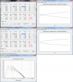
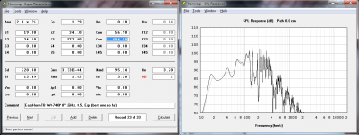
Use less segments and the results will be much worse. As I've mentioned several times I can make a much worse sim than I showed previously. I didn't use Akabak at all for this since it's just a CON vs PAR issue and this issue is worst when only 1 segment is used, so for the sake of saving time and energy I used Hornresp for both sims shown here.
The top row is a CON sim and it's resulting schematic.
In the second row the ONLY thing that is changed is I've changed CON to PAR.
Notice the massive difference in shape and volume.
The third row single pic shows the spl response difference. This is a massive error.
Forget the fact that this isn't a good design and can't actually be built as simmed. This is just an example that things can go horribly wrong if you are forced to use CON and you don't use a lot of segments. As usual, understanding the issue is the key to avoiding problems. This result isn't typical but it's no more atypical than the 48 segment comparison you just linked to, since most people just use Akabak to add 1 or 2 segments, not 44.
How's that for a crux?
Edit - I added another example. The only difference is CON vs PAR.
If you use an infinite number of segments (or even a segment for every mm of path length) the Akabak results will overlay a 4 segment Hornresp sim so closely that with the naked eye you could call it perfectly overlaid.
Use less segments and the results will be much worse. As I've mentioned several times I can make a much worse sim than I showed previously. I didn't use Akabak at all for this since it's just a CON vs PAR issue and this issue is worst when only 1 segment is used, so for the sake of saving time and energy I used Hornresp for both sims shown here.
The top row is a CON sim and it's resulting schematic.
In the second row the ONLY thing that is changed is I've changed CON to PAR.
Notice the massive difference in shape and volume.
The third row single pic shows the spl response difference. This is a massive error.
Forget the fact that this isn't a good design and can't actually be built as simmed. This is just an example that things can go horribly wrong if you are forced to use CON and you don't use a lot of segments. As usual, understanding the issue is the key to avoiding problems. This result isn't typical but it's no more atypical than the 48 segment comparison you just linked to, since most people just use Akabak to add 1 or 2 segments, not 44.
How's that for a crux?
Edit - I added another example. The only difference is CON vs PAR.
Attachments
Last edited:
That's what I do but it's not fun being locked into having to do that to get the most accurate results possible when you only really need 1 or 2 more segments than Hornresp can provide. A simple Akabak import turns into a huge job.
I had really high hopes for the new tl.app program but it appears to be abandoned so it's probably not a good idea to get too attached.
I had really high hopes for the new tl.app program but it appears to be abandoned so it's probably not a good idea to get too attached.
Last edited:
Hi David_Web,
To a degree, yes. The programming language used also plays a part in how fast things are processed.
I'm not sure how much more time I really want to spend on the wizard - as I said at the outset, filters are of limited interest to me.
It could be done, but would complicate the operation of the overall program - highly unlikely this stage.
Kind regards,
David
Wouldn't realtime update depend on how powerful computer is?
To a degree, yes. The programming language used also plays a part in how fast things are processed.
You could have a checkbox (or setting) to enable additional stuff to be shown. That would leave the wizard responsive for slower machines.
I'm not sure how much more time I really want to spend on the wizard - as I said at the outset, filters are of limited interest to me
. Would it be possible to have the filters enabled(optional) in loudspeaker wizard so that you could design response with crossover in mind?
It could be done, but would complicate the operation of the overall program - highly unlikely this stage
.Kind regards,
David
Hornresp Update 3210-130428
Hi Everyone,
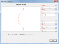
A tool has been added to calculate the air volume in front of the driver diaphragm. This should make things a bit easier when dimensioning throat chambers.
The tool calculates the effective air volume between the driver diaphragm and the front plane of the driver, given the inside diameter of the mounting sealing strip, the inside diameter of the diaphragm suspension, the diameter of the dust cap, the thickness of the sealing strip, the perpendicular distance from the front plane to the edge of the dust cap, and the perpendicular distance from the front plane to the centre of the dust cap.
The Tools menu command is enabled when the input parameters window is in edit mode. The tool can also be selected by double-clicking the Vtc or Atc label or text box in edit mode.
Kind regards,
David
Hi Everyone,
A tool has been added to calculate the air volume in front of the driver diaphragm. This should make things a bit easier when dimensioning throat chambers.
The tool calculates the effective air volume between the driver diaphragm and the front plane of the driver, given the inside diameter of the mounting sealing strip, the inside diameter of the diaphragm suspension, the diameter of the dust cap, the thickness of the sealing strip, the perpendicular distance from the front plane to the edge of the dust cap, and the perpendicular distance from the front plane to the centre of the dust cap.
The Tools menu command is enabled when the input parameters window is in edit mode. The tool can also be selected by double-clicking the Vtc or Atc label or text box in edit mode.
Kind regards,
David
Attachments
That will save a fair bit of calculation!
Much appreciated David.
Very useful for finessing horns.
Now that I have been playing with it I find it very intuitive.
At first I did not understand the dimension designations. But there is that little blue bar that shows what dimension is active.
I like it!
I like it alot
Much appreciated David.
Very useful for finessing horns.
Now that I have been playing with it I find it very intuitive.
At first I did not understand the dimension designations. But there is that little blue bar that shows what dimension is active.
I like it!
I like it alot
Last edited:
One question, is it possible to expand the tool with magnet dimensions so it can compensate for the volume, taken by the driver, at S4?
+1
David,
thank you for the driver volume tool, and of course the filter tools.
The calculator you have developed seems entirely appropriate when designing for front loaded horns and symmetrical tapped horn designs.
As you are probably aware, we have been playing around with the concept of accounting for the driver volume and the idea of 'cone compensation', and that some builders have reported positive results that seem to be close to the Hornresp simulation.
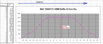
I wonder what your thoughts were on the technique that was developed for offset horns and conventional (asymmetric) tapped horns. In these horn types the horn path moves across the speaker cone instead of away from it. In these cases the point of interest was the cross sectional area of the speaker diaphragm volume and baffle cutout at S2 and the in the case of tapped horns the corresponding loss in area that occurs at S4 due to the speaker diaphragm magnet and chassis.
The cross sectional area of the speaker and cut out are not accounted for in the sim they are compensated for in the physical layout of the horn path. The areas need to be calculated to achieve this, not the volume.
As such there is nothing that you need to add to your excellent program. I was interested in your opinion.
I attach a example plot of the cross sectional area of a speaker diaphragm and baffle cut out showing the change in volume along the hornpath as it travels across the speaker cone.
Kind regards Martin (Xoc1)
thank you for the driver volume tool, and of course the filter tools.
The calculator you have developed seems entirely appropriate when designing for front loaded horns and symmetrical tapped horn designs.
As you are probably aware, we have been playing around with the concept of accounting for the driver volume and the idea of 'cone compensation', and that some builders have reported positive results that seem to be close to the Hornresp simulation.
I wonder what your thoughts were on the technique that was developed for offset horns and conventional (asymmetric) tapped horns. In these horn types the horn path moves across the speaker cone instead of away from it. In these cases the point of interest was the cross sectional area of the speaker diaphragm volume and baffle cutout at S2 and the in the case of tapped horns the corresponding loss in area that occurs at S4 due to the speaker diaphragm magnet and chassis.
The cross sectional area of the speaker and cut out are not accounted for in the sim they are compensated for in the physical layout of the horn path. The areas need to be calculated to achieve this, not the volume.
As such there is nothing that you need to add to your excellent program. I was interested in your opinion.
I attach a example plot of the cross sectional area of a speaker diaphragm and baffle cut out showing the change in volume along the hornpath as it travels across the speaker cone.
Kind regards Martin (Xoc1)
Attachments
- Home
- Loudspeakers
- Subwoofers
- Hornresp