Posts #3077 and 3078
Hi David,
Thanks for taking a look at it. I was just hoping, that because you had already done something similar with the CH simulation model it might not be too involved, but here I am talking like the blind man about colour.
I have been using AkAbak for this, my only problem is, that there are no schematic diagrams or other forms of feedback in that program, and the more complex the simulation, the more difficult to know if I'm actually simulating what I'm trying to simulate (unless I already know the end result). I'll just have to spend more time with AkAbak.
Regards,
I noticed some kind of 'sudden jump' when sliding Vrc and the appearance of 'Helmholtz freq' in the lower right corner. (red color)
The graph suddenly changes a lot too.
Hi Bart,
When a Helmholtz frequency is shown in Hornresp, it means that the dimensions of the vented-box enclosure and the associated port tube are such that the air in the tube (including appropriate end corrections) can be treated as an acoustic mass, and that the system acts as a pure Helmholtz resonator.
When a Helmholtz frequency is not given it means that the port tube is relatively long, and that it acts as a cylindrical horn rather than as a simple lumped acoustic mass. Rather than being a bass-reflex speaker, the system in effect becomes a back-loaded horn with a very large throat chamber. This can be readily confirmed by actually modelling the system as a back-loaded horn - the combined response results will be identical.
It just so happens that in your particular example, increasing the enclosure volume from 273.8 to 273.9 litres changes the port tube from the cylindrical horn model to the acoustic mass model. This is the reason for the 'sudden jump' in the combined SPL response. Very few bass-reflex speakers would normally have a port tube 1.1 metres in length, so the discontinuity seen at the model change threshold is unlikely to be a material issue when using Hornresp to analyse a practical bass-reflex design.
Kind regards,
David
Attachments
Posts #3077 and 3078Thanks for taking a look at it. I was just hoping, that because you had already done something similar with the CH simulation model it might not be too involved, but here I am talking like the blind man about colour.
I have been using AkAbak for this, my only problem is, that there are no schematic diagrams or other forms of feedback in that program, and the more complex the simulation, the more difficult to know if I'm actually simulating what I'm trying to simulate (unless I already know the end result).
Hi Oliver,
Rest assured, if it was not difficult to fully integrate the functionality, I would have included it in a heartbeat
") .
.As far as AkAbak is concerned, I find it quite helpful to draw network diagrams (with numbered nodes) for the more complex system configurations (in effect an extension of the simple diagram included in the Hornresp exported script). It makes it much easier to keep track of things.
Kind regards,
David
Thank you David.
The long port is to have a port surface as big as possible while staying under a quarter wave lenght of the highest frequency the box has to provide.(±80hz)
It has been a balance between first port resonance and largest possible port.
I hope this doesn't mean my box works wrong or with artefacts because of other reasons unknown to me.
When simulating OD horns I'm using Ap1/Lpt to control the entry into the horn at the S2 location, and this seems to work. I would like to additionally have the ability to simultaneously provide a vent for the rear chamber, similar to the way you solved this for CH, by using S4/S5/L45 for the rear chamber port/horn.
Hi Oliver,
Further to my earlier comments...
For your OD design, use Ap and Lpt to specify the vented rear chamber port rather than Ap1 and Lpt to specify the throat chamber port. Not having the throat chamber port in the simulation model will make very little difference to the combined SPL response predicted results.
If you really want to take into account the minimal effect of the throat chamber port, then export the AkAbak script for the OD horn with Ap and Lpt specified, and manually add in an extra Duct element after the existing throat chamber duct to represent the throat chamber port.
Kind regards,
David
I hope this doesn't mean my box works wrong or with artefacts because of other reasons unknown to me.
Hi Bart,
The Hornresp predictions should be reasonably accurate. It may be worthwhile calculating the results with resonances unmasked though, to avoid any nasty surprises.
Kind regards,
David
Just Thanks (no enhancement requests--honest)
Every time I catch some idea and start simming again, I visit this thread only to find out I'm another few revs behind and there are gifts of new features & bugfixes (and it still runs in wine!). David, I can't thank you enough--sincerely. I've had so much fun messing in your program over the years and I've learned a great deal.
Every time I catch some idea and start simming again, I visit this thread only to find out I'm another few revs behind and there are gifts of new features & bugfixes (and it still runs in wine!). David, I can't thank you enough--sincerely. I've had so much fun messing in your program over the years and I've learned a great deal.
Every time I catch some idea and start simming again, I visit this thread only to find out I'm another few revs behind and there are gifts of new features & bugfixes (and it still runs in wine!). David, I can't thank you enough--sincerely. I've had so much fun messing in your program over the years and I've learned a great deal.
Hi grindstone,
Many thanks for your kind comments - you have made my day
. I am particularly pleased to hear that Hornresp has proved to be a helpful and enjoyable-to-use learning tool for you, as that is exactly what I wanted to achieve with the program.Kind regards,
David
A little Show and tell overture
I do quite a bit of design work for different clients. From time to time we do take the designs to prototype and then production. I like to share the following screens. It is simulating and measurement of a very interesting variant on a mass loaded transmission line. No large labyrinth required, just a variant on the venting.


Magnitude of the impedance are not always the same. But they are in remarkably similar locations. Desired tuning frequency at the zero crossing point is spot on. Not bad for a program designed to simulate horns being used to simulate a whacky type of port!
It shows to me that the fundamental theory behind Hornresp is spot on. I describes what air is doing under the influence of a driver. Almost universal in it attribution to speaker design.
What did i do before Hornresp?
Lots of calculating!
And many more mistakes.
I do quite a bit of design work for different clients. From time to time we do take the designs to prototype and then production. I like to share the following screens. It is simulating and measurement of a very interesting variant on a mass loaded transmission line. No large labyrinth required, just a variant on the venting.
Magnitude of the impedance are not always the same. But they are in remarkably similar locations. Desired tuning frequency at the zero crossing point is spot on. Not bad for a program designed to simulate horns being used to simulate a whacky type of port!
It shows to me that the fundamental theory behind Hornresp is spot on. I describes what air is doing under the influence of a driver. Almost universal in it attribution to speaker design.
What did i do before Hornresp?
Lots of calculating!
And many more mistakes.
I wish to echo that sentiment. Hornresp is a wonderful tool and gives me nearly WYSIWYG results when designing front loaded bass horns.
Thanks maxmercy
.Kind regards,
David
It is simulating and measurement of a very interesting variant on a mass loaded transmission line.
Hi Mark,
Thanks for sharing. It is always nice when the measured results line up reasonably well with the predictions
.Kind regards,
David
Yes. Hornresp is scary accurate considering the numerous variables that we don't simulate.
Here is a TH I made with the lovely B&C 15PE40 measured at the opening.
*edit* grey trace is with added resistance to show it behaving differently than creating the hump.
Not entirely sure why there is a hump in the response as it's spot on below the passband meaning it's not room gain. Not a bad one though.
I have not made any far field measurement yet so I can not separate it from the room.
According to AkAbak it gives gain in the entire passband by over 2 when comparing excursion of the driver vs opening. Something a BR can't do.
Here is a TH I made with the lovely B&C 15PE40 measured at the opening.
An externally hosted image should be here but it was not working when we last tested it.
*edit* grey trace is with added resistance to show it behaving differently than creating the hump.
Not entirely sure why there is a hump in the response as it's spot on below the passband meaning it's not room gain. Not a bad one though.
I have not made any far field measurement yet so I can not separate it from the room.
According to AkAbak it gives gain in the entire passband by over 2 when comparing excursion of the driver vs opening. Something a BR can't do.
Last edited:
I also want to thank you David for this wonderful tool. I use it whenever I can for my projects. Simulations are very accurate!
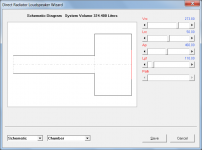
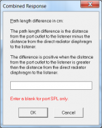
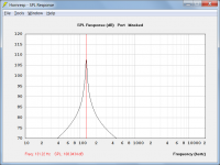
My friend Asto found out that you can use Hornresp for Helmholz calculations (and visualisation), this is how to do it:
I would like to add Helmholz Q calculation to the wishlist.
My friend Asto found out that you can use Hornresp for Helmholz calculations (and visualisation), this is how to do it:
An externally hosted image should be here but it was not working when we last tested it.
An externally hosted image should be here but it was not working when we last tested it.
An externally hosted image should be here but it was not working when we last tested it.
I would like to add Helmholz Q calculation to the wishlist.
The Helmholtz trick is brilliant!
Also I think I found a possible reason for the hump seen in my last post.
IIRC the amp I used to measure had a coupling cap as it was SE chipamp.
Adding a cap in AkAbak did get a rising response similar to the green trace. That + maybe some room interaction could be the key to the mystery.
You have to have a pretty large cap for the change vs bare wire to be insignificant.
Here is a TH I made with the lovely B&C 15PE40 measured at the opening.
Hi David_Web,
Thanks for the feedback.
The measured versus predicted comparison looks good - particularly after seeing the explanation for the hump in your follow-up post
.Kind regards,
David
My friend Asto found out that you can use Hornresp for Helmholz calculations (and visualisation), this is how to do it:]
I would like to add Helmholz Q calculation to the wishlist.
Hi more10,
Thanks for detailing this process.
The port output can of course be shown on the main SPL response chart if so desired - it is not essential to use the Loudspeaker Wizard tool.
I have no plans to provide specific quality factor information in Hornresp. A good indication of the port Q can be gained from your chart, however.
Kind regards,
David
Attachments
Hornresp Update 3100-130120
Hi Everyone,
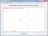
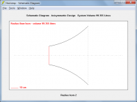
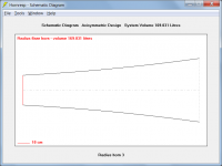
Hornresp can now model radius horns. See http://www.diyaudio.com/forums/subwoofers/226410-horn-flare.html for background information. To select Rad flare in edit mode, press R when the L12 length parameter has the focus. Three sample profiles are attached.
Could you please let me know if you find any bugs.
Kind regards,
David
Hi Everyone,
Hornresp can now model radius horns. See http://www.diyaudio.com/forums/subwoofers/226410-horn-flare.html for background information. To select Rad flare in edit mode, press R when the L12 length parameter has the focus. Three sample profiles are attached.
Could you please let me know if you find any bugs.
Kind regards,
David
Attachments
An externally hosted image should be here but it was not working when we last tested it.
When hitting
An externally hosted image should be here but it was not working when we last tested it.
As you can see, the L12 field is not editable:
An externally hosted image should be here but it was not working when we last tested it.
- Home
- Loudspeakers
- Subwoofers
- Hornresp