For space reasons the combined response chart no longer has the word "Combined" in the title – either "Masked" or "Unmasked" is shown instead.
The attached worst-case examples show more clearly why it was necessary to omit "Combined" from the combined response chart title.
Kind regards,
David
Attachments
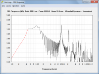
Still like the performance and power out of your example horn setup David.
Thanks Mark. As you can imagine, finding a driver with a Pmax of 9999 W and Xmax of 99.9 mm took quite some doing
") .
.Kind regards,
David
Is there any chance of adding more complex 3 part inductance modeling to HR?
Hi Josh,
Sorry, no chance - I like to keep things as simple as possible
.Kind regards,
David
David
Is there any chance of adding Helmholz chambers in between segments? This would be very useful when trying to supress resonances in transmission lines.
Is there any chance of adding ports in between segments? This would be very useful for simulation of some bass reflex enclosures. I would like to simulate swapping placement of port and driver in JBL 2226 ported something I built from srx boxes
And thanks for your fantastic software!
Last edited:
All I want for Christmas is....
David
I am fully aware of your stance on adding a signal filter function to Hornresp and when I mentioned the lack of same on the other thread I did not make a request directly to you.
http://www.diyaudio.com/forums/subw...ferents-simulation-sofware-2.html#post3280268
But since this is the place to discuss these things I will post my reasons here:-
Most systems do not have a flat signal to 10Hz, for most audio systems such an extended LF would result in driver damage.
For bass reflex designs and tapped horns, a hi-pass filter is a necessity above a fairly low power level, and must be concidered as an integral part of the design process.
There is also the QB5 reflex alignment that uses a port tuned for a resonant peak and a filter to reduce cone excursion and give a resultant extended flat reponse.
Satellites and Subwoofers
I do feel that it would be a great addition to your software and would result in some very creative designs.
Kind regards
Martin (Xoc1)
Hi Khron,
Sorry, but I have no plans to add incoming signal filtering functionality to Hornresp.
My interest lies with the performance of the loudspeaker itself - not with how the signal is processed prior to reaching the loudspeaker
Kind regards,
David
David
I am fully aware of your stance on adding a signal filter function to Hornresp and when I mentioned the lack of same on the other thread I did not make a request directly to you.
http://www.diyaudio.com/forums/subw...ferents-simulation-sofware-2.html#post3280268
But since this is the place to discuss these things I will post my reasons here:-
Most systems do not have a flat signal to 10Hz, for most audio systems such an extended LF would result in driver damage.
For bass reflex designs and tapped horns, a hi-pass filter is a necessity above a fairly low power level, and must be concidered as an integral part of the design process.
There is also the QB5 reflex alignment that uses a port tuned for a resonant peak and a filter to reduce cone excursion and give a resultant extended flat reponse.
Satellites and Subwoofers
I do feel that it would be a great addition to your software and would result in some very creative designs.
Kind regards
Martin (Xoc1)
hi martin
i opted a simular question a few pages back.
Thats easy to do: You only need to convert the HR textfile to a format that any of these program can recognize:
FRD Consortium
PS: I usually first import the .wav files from HR to HOLMimpulse where I edit the IR/FR and then export to e.g. MPRM program where you can do all filtering/ Eq. and the back to Holmimpulse to present the resulting graphs you want to display.
b

i opted a simular question a few pages back.
Hi epa,Quote:
Originally Posted by epa
hi david
is there any sofware that you (or anybody else)now of ,that can import hr data ,to model a filter/eq .
this would be helpfull to determen a hpf.
tnx erik
Thats easy to do: You only need to convert the HR textfile to a format that any of these program can recognize:
FRD Consortium
PS: I usually first import the .wav files from HR to HOLMimpulse where I edit the IR/FR and then export to e.g. MPRM program where you can do all filtering/ Eq. and the back to Holmimpulse to present the resulting graphs you want to display.
b
WAY COOL!
I had no idea this was possible.
I couldn't get it to work in my favorite FRD tool (assymmetrical response pattern estimator) but I *was* able to get it to work in Bagby's xover simulator.
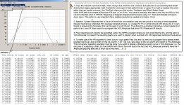
Here's how I did it (very easy)
1) to get the FRD file, open your hornresp design's frequency response plot. Then export the plot as a text file.
2) to get the ZMA file, do the same thing as step 1, but do it using the impedance plot, instead of the frequency response plot.
The last step is that you have to comment out the first line of the file. Do that by typing "*" at the beginning of the line.
That's it!
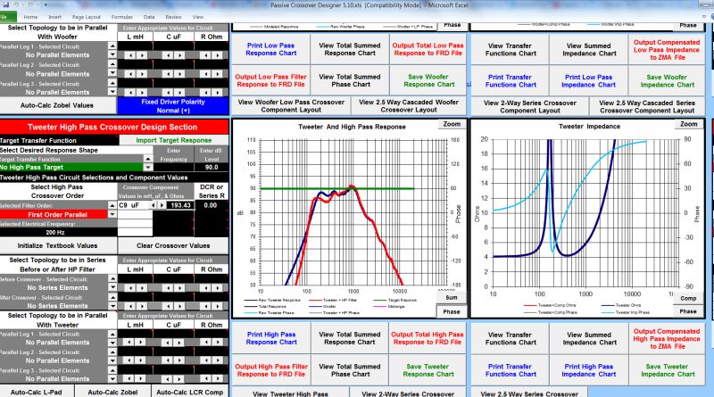
Here's a Paraline simmed in Bagby's xover simulator:
I had no idea this was possible.
I couldn't get it to work in my favorite FRD tool (assymmetrical response pattern estimator) but I *was* able to get it to work in Bagby's xover simulator.
Here's how I did it (very easy)
1) to get the FRD file, open your hornresp design's frequency response plot. Then export the plot as a text file.
2) to get the ZMA file, do the same thing as step 1, but do it using the impedance plot, instead of the frequency response plot.
The last step is that you have to comment out the first line of the file. Do that by typing "*" at the beginning of the line.
That's it!
Here's a Paraline simmed in Bagby's xover simulator:
hi martin
i opted a simular question a few pages back.
Hi epa,
Thats easy to do: You only need to convert the HR textfile to a format that any of these program can recognize:
FRD Consortium
PS: I usually first import the .wav files from HR to HOLMimpulse where I edit the IR/FR and then export to e.g. MPRM program where you can do all filtering/ Eq. and the back to Holmimpulse to present the resulting graphs you want to display.
b
Adding
 , If you collect more, not necessarily from my contributions: In future you will be rich
 Attachments
... For bass reflex designs and tapped horns, a hi-pass filter is a necessity above a fairly low power level, and must be concidered as an integral part of the design process.
There is also the QB5 reflex alignment that uses a port tuned for a resonant peak and a filter to reduce cone excursion and give a resultant extended flat reponse. ...
There's no one program that I am aware of that does it all "in the box".
For classic enclosure topologies (sealed, ported, bandpass), Brian Steele's "Ported" spreadsheet from diysubwoofers.org has a comprehensive set of built-in filters. I use it for experimenting with non-standard alignments such as QB5 and for enclosures for car use.
Kristian Ougaard's Unibox spreadsheet allows importing an active filter response in .frd file format.
AkAbak allows defining active (and passive) filters. You can define active filters to place inline with the driving signal, and passive filters (inductors, cpacitors, resistors) to place inline with the drivers. The active filters can either be "black box" (defined response) or built from components (op-amps, R, L , C).
I usually use Ported or Hornresp to get a design "in the ballpark", then export it to AkAbak for refinement if it shows promise.
Is there any chance of adding Helmholz chambers in between segments? Is there any chance of adding ports in between segments?
Hi more10,
Unfortunately I cannot justify the amount of work required to add the above features to Hornresp, particularly as they are already available in AkAbak.
At the very minimum, major changes would be required to the input parameters screen, the schematic diagram, the loudspeaker wizard, and the AkAbak script export tool.
Kind regards,
David
I do feel that it would be a great addition to your software and would result in some very creative designs.
Hi Martin,
Sorry, but there is nothing that anyone can say (no matter how compelling the argument) that will cause me to change my mind with regard to electrical filters in Hornresp.
I do give you full marks for trying, though
.There is always AkAbak, of course...
Kind regards,
David
I havent read this whole thread, but would like to know if i can simulate multiple drivers into a single horn, like two of the same driver with a common throat/mouth.
what i was thinking was if one had an Sd of 310, would it be as simple as changing it to 620? would i also need to change anything like Fs or Vas? ect?
what i was thinking was if one had an Sd of 310, would it be as simple as changing it to 620? would i also need to change anything like Fs or Vas? ect?
I havent read this whole thread, but would like to know if i can simulate multiple drivers into a single horn, like two of the same driver with a common throat/mouth.
what i was thinking was if one had an Sd of 310, would it be as simple as changing it to 620? would i also need to change anything like Fs or Vas? ect?
Hi klampykixx,
Enter the driver parameter values for a single driver, and then select the Tools > Driver Arrangement menu command from the Input Parameters window when in Edit mode.
It is not necessary for the user to manually adjust any of the driver parameter values to account for multiple drivers - Hornresp does this internally, automatically.
Kind regards,
David
Hi klampykixx,
When you use the Driver Arrangement tool, that is correct.
If by "post calc section" you are referring to using the Multiple Speakers tool, then please note that this tool allows multiple horns to be specified, not multiple drivers. By using both the Driver Arrangement tool and the Multiple Speakers tool together, it is possible (for example) to have two horns connected in parallel, with each horn containing two drivers connected in series.
Kind regards,
David
ok, so that will act as two or more drivers in the same horn as is simulated,
When you use the Driver Arrangement tool, that is correct.
edit: just tried it in both pre calculated section and post calc section. it definately changes things. thanks
If by "post calc section" you are referring to using the Multiple Speakers tool, then please note that this tool allows multiple horns to be specified, not multiple drivers. By using both the Driver Arrangement tool and the Multiple Speakers tool together, it is possible (for example) to have two horns connected in parallel, with each horn containing two drivers connected in series.
Kind regards,
David
- Home
- Loudspeakers
- Subwoofers
- Hornresp