Thanks David!
I just tried it on a midrange horn I'm fooling around with. It is quite intuitive. Thanks for the suggestion Bjørn.
It's not the wizard, but it is really quite fast.
The new help format is indeed easier to read as well.
Thanks again David. These refinements are making a powerful program easier to use. All a big bonus!


Santa???? I think it's really David.
Hi Mark,
How did you ever guess?
See my photo below - I told you I was old...
") .
.Kind regards,
David (aka Santa)
Attachments

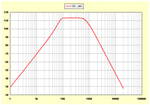
Frequencies below 10 hertz can of course be individually sampled, and the results manually added to the exported chart data for plotting in Excel or similar, if so desired.
To illustrate, the attached chart shows the default record constant directivity SPL response (with chamber resonances masked) plotted down to 1 hertz.
Kind regards,
David
Attachments
Does this confirm that 4 horns are required to reproduce the 20Hz to 20kHz audio bandwidth?
No.
-Bjørn
More than 2½ octaves from that horn.
Does this confirm that 4 horns are required to reproduce the 20Hz to 20kHz audio bandwidth?I have a job where I'm doing it with three horns. And if you can cut down the low end to about 80 hz you can pull it off with two horns.
Unfortunately for some reason on trying to run it, i get this error?
Hi Zero D,
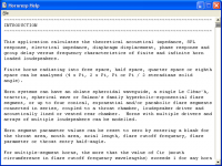
Simply select 'Hornresp Help' from the 'Help' menu or press the F1 function key, as for the previous version. Don't attempt to open the Hornresp.hlp file yourself.
As indicated in the Readme.txt file, Hornresp.exe and Hornresp.hlp need to be placed in the same folder.
Kind regards,
David
Hornresp Update
Hi Everyone,
A minor cosmetic change has been made to the new Help file. A one-character-wide margin has been added to the left, similar to the one already existing on the right. My thanks to Bjørn for the suggestion (via e-mail). It improves the appearance and readability of the text window quite nicely.
Product Number 2890-111221 refers.
Kind regards,
David
Attachments
If you're going to specify a rear chamber in this case, wouldn't a very large rear chamber be the way to go? This would have the least effect on the speaker which is the desired result as opposed to a small rear chamber which would have a large effect on the driver's stiffness and would not be accurate. This is assuming you do not know the T/S parameters of the driver without the sealed rear chamber and don't want to calculate fictitious parameters.
I think John has the right idea here. Generally I go with option B - calculate fictitious parameters. For instance, 90% of the 'sealed back' midranges are in a range of drivers which also include an 'open back' model. So I use the 'open back' model to guesstimate the 'closed back' model, then tweak the parameters until they're sensible. (IE, adjust enclosure volume until the impedance curve matches the closed back version, particularly the Fb)
Hornresp artifact or bug?. Some misteries

Xmax= 3mm causes clipping
Hornresp 28.90 (2890-11218) script:
First mistery: frecuency ripple increases.

SPL and ripple increases when SPL Maximum is enabled. However there is no clipping because Xmax = 33 mm. Is this behaviour ok?
Xmax= 3mm causes clipping
Second mistery: displacement increases

No clipping when Xmax = 33mm. Nevertheless displacement increases under SPL Maximum request. WHY?
No clipping when Xmax = 33mm. Nevertheless displacement increases under SPL Maximum request. WHY?
Hornresp 28.90 (2890-11218) script:
ID=28.80
Ang=0.5 x Pi
Eg=2.83
Rg=0.30
Cir=0.89
S1=92.00
S2=92.00
Con=40.00
F12=0.00
S2=92.00
S3=15000.00
Exp=557.79
F23=25.00
S3=0.00
S4=0.00
L34=0.00
F34=0.00
S4=0.00
S5=0.00
L45=0.00
F45=0.00
Sd=138.80
Bl=7.12
Cms=5.27E-03
Rms=0.50
Mmd=9.10
Le=1.13
Re=6.20
Nd=1
Vrc=11.00
Lrc=10.80
Fr=8.30
Tal=1.20
Vtc=2000.00
Atc=495.80
Pmax=100
Xmax=5.0
Comment=GB-Audio B-6K
Last edited:
I'm wondering if there's a way or possibility to simulate in HR waveguide fine-tune end elements like used in organ pipes like this:
An externally hosted image should be here but it was not working when we last tested it.
You can add a segment to the mouth, but I don't think it will effectively "simulate" the 3rd, fourth, and fifth configurations. All appear to compromise the performance of the device. I would think the effective way to fine tune a waveguide would be to shorten it from the mouth end unlike the examples you have shown.
In fact this sort of traditional in organ pipes fine-tune endings can not only serve to adjust/tuning but also influences the final acoustical impedance at the end of the waveguide.
And as we cannot know with absolute precision the final effect at simulation stage, this possibility can be helpful in fine tuning the end result without re-constructing the whole thing.
And as we cannot know with absolute precision the final effect at simulation stage, this possibility can be helpful in fine tuning the end result without re-constructing the whole thing.
Hi amjulio,
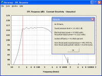
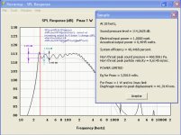
The SPL and ripple increase when the Maximum SPL tool is used because the acoustical output power is greater.
For the default SPL response at 28 hertz, the electrical input power is 0,5409 watts (Eg = 2,83 volts) and the acoustical output power is 0,2222 watts - see attached screenprint. For the Maximum SPL response at 28 hertz, the electrical input power is 1,0000 watt (Pmax = 1 watt) and the acoustical output power is 0,4108 watts. The system efficiencies in each case are the same (41,0826 percent).
For the same reason as above - the displacement increases when the Maximum SPL tool is used because the electrical input power is greater.
It is important to remember that the default SPL response uses a constant voltage source, whereas the Maximum SPL response (when not displacement limited) uses a constant power source - the results, as you have observed, can be quite different for the two cases.
Kind regards,
David
SPL and ripple increases when SPL Maximum is enabled. However there is no clipping because Xmax = 33 mm. Is this behaviour ok?
The SPL and ripple increase when the Maximum SPL tool is used because the acoustical output power is greater.
For the default SPL response at 28 hertz, the electrical input power is 0,5409 watts (Eg = 2,83 volts) and the acoustical output power is 0,2222 watts - see attached screenprint. For the Maximum SPL response at 28 hertz, the electrical input power is 1,0000 watt (Pmax = 1 watt) and the acoustical output power is 0,4108 watts. The system efficiencies in each case are the same (41,0826 percent).
No clipping when Xmax = 33mm. Nevertheless displacement increases under SPL Maximum request. WHY?
For the same reason as above - the displacement increases when the Maximum SPL tool is used because the electrical input power is greater.
It is important to remember that the default SPL response uses a constant voltage source, whereas the Maximum SPL response (when not displacement limited) uses a constant power source - the results, as you have observed, can be quite different for the two cases.
Kind regards,
David
Attachments
Hi amjulio,
The SPL and ripple increase when the Maximum SPL tool is used because the acoustical output power is greater.
...
For the same reason as above - the displacement increases when the Maximum SPL tool is used because the electrical input power is greater.
Hi, David
ripple shouldn´t increase when output power is increased:
I wonder if your last remark explain ripple increment. I think it does because constant output power implies not costant output voltage.It is important to remember that the default SPL response uses a constant voltage source, whereas the Maximum SPL response (when not displacement limited) uses a constant power source - the results, as you have observed, can be quite different for the two cases.
Kind regards,
David
What is SPL Maximun for?. Because normal power amplifiers have constant voltage outputs. So the normal output of Hornresp models better reality I think. Am I wrong?
Thanks for you reply.
Attachments
You can add a segment to the mouth, but I don't think it will effectively "simulate" the 2nd, fourth, and fifth configurations. All appear to compromise the performance of the device. I would think the effective way to fine tune a waveguide would be to shorten it from the mouth end unlike the examples you have shown.
In fact this sort of traditional in organ pipes fine-tune endings can not only serve to adjust/tuning but also influences the final acoustical impedance at the end of the waveguide.
And as we cannot know with absolute precision the final effect at simulation stage, this possibility can be helpful in fine tuning the end result without re-constructing the whole thing.
My apollogies for the typo above, I have made the correction in bold
I would think that the need to tune could be more effectively addressed at the mouth end by simply moving the baffle that the inlet piping is attached to. Obviously this would make for more work in the plumbing, however one could use sliding couplings that are common for electrical PVC conduit and the variant that is meant for water lines. Please see the link below for examples.
Search Results for "conduit expansion coupling" at Menards
- Home
- Loudspeakers
- Subwoofers
- Hornresp