horns that are not "full size" break the empirical rules that have been established many decades ago.
The most basic of these non full size is the truncated horn.
One designs the full horn to reproduce the frequency range one is interested in.
To create a truncated horn one chops off the "big end". This shortens the horn length and also massively reduces the mouth area. It breaks the rule on mouth area and it breaks the rule on horn length.
The truncated horn is possibly 50% to 70% of the full horn length, but only 10% of the full horn volume. This makes it practical and affordable.
The clever designer tries different truncations in a variety of different horn designs and decides which he thinks will make him the most from it.
The pro is obvious, smaller horn, but what about the con of 1/2 size ?
It raises the horn's pipe tuning [Fp], cut-off [Fc], ergo reducing its gain bandwidth [BW] due to having a shorter acoustic path-length, larger throat and smaller mouth. All of the Altec 800 series horn cabs and all [AFAIK] its 'copycats' are scaled horns.
GM
virtually every horn purporting to reproduce bass frequencies is a truncated horn.Do you have some links for more explanations or articles about truncated horn ?
Some examples of truncated horn ?
Regards.
Even the enormous, ~600litres, Tannoy Westminster Royale. Or is that HE now?
The clever designer tries different truncations in a variety of different horn designs and decides which he thinks will make him the most from it.
To create a truncated horn one chops off the "big end".
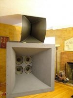
Correct, so the mouth doesn't always get chopped off, i.e. the Altec 200 series theater horns and other manufacturer's variations cut off the small end and use multiple drivers with the right set of specs to arguably get the least compromised overall performing truncation. Admittedly, such horns if not corner loaded can intrude a bit too much into a typical HIFI/HT though:
GM
Attachments
To create a truncated horn one chops off the "big end". This shortens the horn length and also massively reduces the mouth area.
To give an indication of scale - a non-truncated square cross-section 35Hz exponential horn radiating into half space would require a mouth size of about 2 metres x 2 metres. Even when positioned in a corner, the required mouth size would still be about 1 metre x 1 metre.
Kind regards,
David
Hello GM,
Every exponential horn of finite length is truncated and the Altec one you show is such.
I guess you are referring to Keele formula for the optimum mouth diameter.
As clearly said by Björn Kolbrek in his paper in AudioXpress: "Horn Theory" (part 1) you can read at:
http://www.audioxpress.com/magsdirx/ax/addenda/media/kolbrek2884.pdf
"This lead Keele to investigate what the optimum horn mouth size would be (ref.19). For a horn termination simulated by a piston in an infinite baffle, he found the optimum krm to be slightly less than 1, the exact value depending on how close to cutoff the horn is operating. His findings were based on the plane wave assumption, which, as you will see in the next section, does not hold in practice"
"If the same horn is calculated assuming spherical waves, there is no obvious optimum mouth size."
Best regards from Paris, France
Jean-Michel Le Cléac'h
Correct, so the mouth doesn't always get chopped off, i.e. the Altec 200 series theater horns
Last edited:
could you expand on this comment by considering the Tractrix horn?............"If the same horn is calculated assuming spherical waves, there is no obvious optimum mouth size."
Hello,
When the young Voigt in the 20s used to "rework" the exponential horn on the basis of curved wavefront (at the time he could only manage with spherical wavefront due to the lack of computer). He calculated a set of point for several wavefronts and report their coordiantes on a sheet of paper. He used for the calculation, an exponential expansion of the area of the wavefronts as at the time this was the commonest solution of the Webster's equation used.
For any reason, he stopped the calculation when the slope of the profile seemed to become nearly orthogonal to the axis and on the view of that set of points a draftman who was working with Voigt said: this is a "tractrix curve" and for sure a tractrix curve was a good aproximation for the real curve passing through that limited set of points.
You'll find at the end an excerpt of the complete story as told by Bruce Edgar
Now, with the help of computers we can draw the real curve that Voigt should have obtain on the basis of an exponential expansion of spherical wavefronts.
I did the calulation and you'll find in attached file the comparison between the tractrix profile and the recalculated curve.
Only that last curve can lead to infinite or quasiinfinite horns.
The tractrix profile which stops at 90° of the axis has to be considered as a truncated horn.
* * * * * * * * * * * * * * * * * * * * * * * * * * * * * * * * * * * * * * * *
Voigt as cited by Bruce Edgar in POSITIVE FEEDBACK ONLINE - ISSUE 4 (2002)
(copyright Bruce Edgar)
"The only way that he could figure out to make his driver sound good was to horn load it, but he couldn't understand the mathematics behind the exponential, so he said, "Well, the exponential theory predicts that the wave form going down the horn is plane or flat, but if you look at the physics of the situation, the wave front has to drag along the horn walls. So naturally it's going to be curved. What if I geometrically designed a horn that has curved wave fronts all the way through the horn and see what happens?" So he did a geometrical construction of a horn that would give him curved wave fronts. He said that a draftsman looked at what he had done and said, "Oh, that's a Tractrix curve."
Best regards from Paris, France
Jean-Michel Le Cléac'h
could you expand on this comment by considering the Tractrix horn?
Attachments
Last edited:
To give an indication of scale - a non-truncated square cross-section 35Hz exponential horn radiating into half space would require a mouth size of about 2 metres x 2 metres. Even when positioned in a corner, the required mouth size would still be about 1 metre x 1 metre.
Kind regards,
David
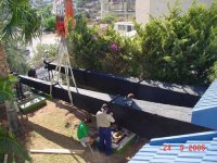
Which is why, in the old days, men used to demolish their living room wall and make the new wall opening the mouth of a horn, extending the horn out to the back yard... If they were really dedicated they buried the driver in the ground...

Hello GM,
Every exponential horn of finite length is truncated and the Altec one you show is such.
I guess you are referring to Keele formula for the optimum mouth diameter.
Greets!
Actually, it's listed on the Lansing Heritage website as a Jim Lansing/Westrex/Ampex theater horn depending on the label stuck to it. Regardless, we must have a frame of reference to decide from which end [or both] to truncate from, so while you’re right referenced to an 'infinite' expansion it seems an impractical one, at least for the purposes of this thread topic.
Not really, Keele wasn't around when I learned that the pioneers of audio had long since concluded before I was born that a 1 WL mouth area of the desired LF response was the practical limit that the horn in the picture represents. Didn't know he even existed until folks started referring to his work decades later on the joelist and still haven't gotten around to reading any of his published work. Ditto BK's thoughts on horn theory. Thanks for the link though!
When someone on the joelist referenced Keele's thoughts on mouth size, I just assumed he subtracted out the mouth end correction which at a glance seems a reasonable thing to do, but my own experiments had already concluded that the 1 WL rule was fine for mid-bass, lower mids horns out to ~600 Hz, so was probably overkill for bass horns, though haven’t actually done any experimenting with < 70 Hz 1 WL mouth areas.
Since you don’t seem to agree with the < 1 WL reference to define being truncated from the mouth, where do you think it should be?
GM
Optimum Horn Mouth Size
As far as designing a horn loudspeaker system in Hornresp is concerned, for those flare profiles that have a defined cutoff frequency, from a practical perspective you can't go too far wrong if the following mouth size conditions are met:
For Exp, Hyp and Obl: Cir = 1 or greater
For Sph and Tra: Fta = 90 degrees
For Lec: Fta = 180 degrees
For Con and Par flare profiles choose a mouth size such that Cir >= 1 when the flare is changed to Exp.
Kind regards,
David
Which is why, in the old days, men used to demolish their living room wall and make the new wall opening the mouth of a horn, extending the horn out to the back yard...
Hi dirkwright,
Not just in the old days...
.Kind regards,
David
Attachments
When I use your system designer, the window that pops up with the low frequency cutoff and high frequency roll off are filled in. I was wondering how Hornresp comes up with these numbers?
Hi dirkwright,
For the System Design With Driver tool:
f1 = Int(fs / 1.125)
f2 = 10 * f1
Where fs is the driver free-air resonance frequency in hertz.
For the System Design From Specifications tool:
f1 = 40
f2 = 10 * f1
Bear in mind that these are empirical default settings only, intended to act as a suggested starting point. They can be altered by the user as desired.
Kind regards,
David
With f1 and f2 choosen, T is the parameter to be adjusted for achieving reactance annulling.
This strictly follows Leach´s formulas.
Another way to do it(as in my spreadsheet) is to decide f1 and T and then accept/find f2.
It would be great to have the opportunity to decide if inputting T or f2 together with f1 in the "System Designer".
This strictly follows Leach´s formulas.
Another way to do it(as in my spreadsheet) is to decide f1 and T and then accept/find f2.
It would be great to have the opportunity to decide if inputting T or f2 together with f1 in the "System Designer".
With f1 and f2 choosen, T is the parameter to be adjusted for achieving reactance annulling.
This strictly follows Leach´s formulas.
Another way to do it(as in my spreadsheet) is to decide f1 and T and then accept/find f2.
It would be great to have the opportunity to decide if inputting T or f2 together with f1 in the "System Designer".
Is T the same as "M" in the Bruce Edgar articles? For Hyp-Ex horns, M=0.7 was a good value as I recall.
Also, choosing F2 was a function of the chosen driver, or one would chose a driver to achieve the desired F2, based on the high frequency mass rolloff number. For example, the 12PE32 has a mass rolloff of 537Hz, so 500Hz is practical as F2. Back when I designed my first horn 20 years ago, I used the EVM15L driver, with a mass roll off around 500Hz.
I have been using Hornresp for a couple of years now. I am very impressed with it
I am now working on a LeCleac'h horn for a 1" compression driver. Group delay, acoustical impedance and polar map are useful. Spl response is not so useful though
May I suggest a few improvements? I have not read through all 224 pages, so forgive me if this has already been suggested.
I would like to be able to model the phase plug as the first section, the exit of the driver as the second section, an angle adapter as the third section (a spline perhaps as suggested by LeCleac'h himself) and finally the LeCleach horn as the fourth section.
Also entry and exit angles for each section would be useful.
Hi more10,
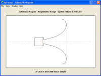
The way that Hornresp has evolved, massive changes would be required to implement the functionality you are seeking. Sorry, but it is not going to happen. The best that you can do is to specify a chamber and throat adaptor using parameters Vtc, Atc, Ap1 and Lpt - see attached screenprint.
To check the throat adaptor half-angle, double-click on the Ap1 input box in edit mode and then press the Calculate button to display the Fta value.
The horn throat entry half-angle is given by AT on the main input screen.
In the example shown, the throat adaptor half-angle has been made equal to the horn throat entry half-angle.
Kind regards,
David
Attachments
- Home
- Loudspeakers
- Subwoofers
- Hornresp